
Catalog excerpts

DUPLOMATIC AUTO M ATI O N TRM-N sries 2* ELECTROMECHANICAL VERTICAL AXIS TURRETS TOOLHOLDERS CLAMPING DIN 69881-1 TECHNICAL INFORMATION - lONet - * * *C * CERTIFICATS I.T. 6440 ISSUED 01-09 The data given in the I.T. are subject to technical modifications without notice.
Open the catalog to page 1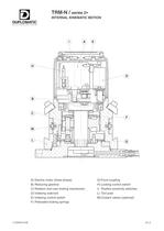
D TRM-N / sries 2* INTERNAL KINEMATIC MOTION DUPLOMATIC AUTOMATION A) Electric motor (three phase) G) Front coupling B) Reducing gearbox H) Locking control switch C) Rotation and cam locking mechanism I) Position proximity switches D) Indexing solenoid L) Tool post E) Indexing control switch M) Coolant valves (optional) F) Preloaded locking springs I.T.6440-0109 A1-2
Open the catalog to page 2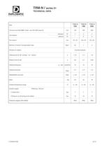
TRM-N / sries 2* TECHNICAL DATA DUPLOMATIC Size TRM-N 120 TRM-N 160 TRM-N 200 Tool post size DIN 69881 sheet 1 (ex VDI 3425 sheet 5) mm 120 160 200 standard Tool stations N° 4 4 4 optional N° - 6 6 Tool section mm 16 x 16 20 x 20 25 x 25 Moment of inertia of transportable mass Kgm 2 0,5 1 3 Direction of rotation Counterclockwise Indexing time for 90° (unclap. - rot. - clamp.) s 1,15 1,4 1,6 Rotation time for 90° s 0,6 0,7 0,85 Indexing frequency a = 90° cycle/min 14 12 10 Indexing accuracy Deg° ± 4" ± 4" ± 4" Repeatability accuracy Deg° ± 1,6" ± 1,6" ± 1,6" Mass ~ Kg 20 42 70 Ambient...
Open the catalog to page 3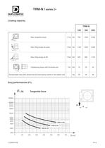
TRM-N / sries 2* DUPLOMATIC AUTQMATION Loading capacity F1 Max. tangential torque F1xb Nm 120 TRM-N 160 200 700 1.500 2.900 1.100 1.600 2.800 550 900 1.750 10 25 45 30 50 90 b Max. tilting torque (to push) F2xb Nm b Max. tilting torque (to lift) F3xb Nm [__b_ E) P -1 Unbalancing torque with horizontal axis PxL Nm L Kg Transportable mass with vertical axis and load gravity centre on the rotation axis Duty performances (F1) F1 [N] Tangential force Fi > b 200000 100000 80000 60000 40000 20000 10000 8000 6000 4000 2000 1000 0 100 200 300 400 500 600 700 b [mm] I.T.6440-0109 A1-4
Open the catalog to page 4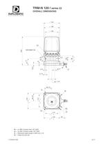
TRM-N 120 / sries 22 OVERALL DIMENSIONS DUPLOMATIC AUTQMATIQN $ 144 CM + J!_1 65,75 U R 4 41 144 35 R (or R1) Coolant inlet 1/8" GAS U 闗 (or U1) Coolant outlet 1/8" GAS C Electrical cable lenght 2.000 mm 0 15 D ח Holes for pins 06 I.T.6440-0109 A1-7
Open the catalog to page 7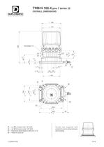
TRM-N 160-4 pos. / sries 23 OVERALL DIMENSIONS DUPLOMATIC AUTOMATION R (or R1) Coolant inlet 1/8" GAS U 闗 (or U1)Coolant outlet 1/8" GAS C Electrical cable lenght 2.000 mm 0 15 D ח Holes for pins 08 Turrets are supplied with protection wire brushes between and housing I.T.6440-0109 A1-8
Open the catalog to page 8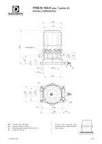
TRM-N 160-6 pos. / sries 23 OVERALL DIMENSIONS DUPLOMATIC AUTQMATIQN 0 188 $ 172 r~ 4--^. CD CM CD DIN 69881-72 1 M_c,"_c il i 鮮Brtx- 1 C D m ^> ION <MM o 1-1- n Il I I j 230 R1 Coolant inlet 1/8" GAS U1 ח Coolant outlet 1/8" GAS C Electrical cable lenght 2.000 mm 0 15 D ח Holes for pins 08 Turrets are supplied with protection wire brushes between and housing I.T.6440-0109 A1-9
Open the catalog to page 9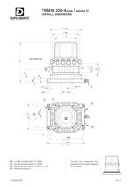
TRM-N 200-4 pos. / sries 23 OVERALL DIMENSIONS DUPLOMATIC AUTQMATION R (or R1) Coolant inlet 1/4" GAS U 闗 (or U1)Coolant outlet 1/4" GAS C Electrical cable lenght 2.000 mm 0 15 D ח Holes for pins 010 Turrets are supplied with protection wire brushes between and housing I.T.6440-0109 A1-10
Open the catalog to page 10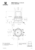
TRM-N 200-6 pos. / sries 23 OVERALL DIMENSIONS DUPLOMATIC AUTQMATIQN 0 232 0 200 ii + O O i_i CB || CD | || |n I ii 262 288 R1 Coolant inlet 3/8" GAS U1 闗 Coolant outlet 3/8" GAS C Electrical cable lenght 2.000 mm 0 15 D ח Holes for pins 010 Turrets are supplied with protection wire brushes between and housing I.T.6440-0109 A1-11
Open the catalog to page 11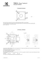
TRM-N - 4 pos. / sries 2* COOLANT CIRCUIT DUPLOMATIC AUTQMATION STANDARD VERSION fig. 1 Each turret has two inlets for the coolant, respectively R and R1, fitted on the base plate. The coolant passes from the base to the turret housing through the two valves V and V1 fed by inlets R and R1. A coolant outlets are, on the top of tool post: R - U ; R1 - U1. OPTIONAL VERSION El E3 fig. 2 fig. 3 fig. 4 As optional the TRM-N 160/200 turrets can be equipped with "E" valves (three valves for each turret side), for the outlet of coolant directly on the toolholder (fig. 2). The working of the valve...
Open the catalog to page 12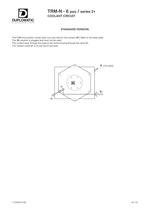
TRM-N - 6 pos. / sries 2* COOLANT CIRCUIT DUPLOMATIC STANDARD VERSION The TRM-N-6 position turrets have one only inlet for the coolant (R1) fitted on the base plate. The (R) position is plugged and must not be used. The coolant pass through the base to the turret housing through the valve V1. The coolant outlet U1 is on the top of tool post. (not used) I.T.6440-0109 A1-13
Open the catalog to page 13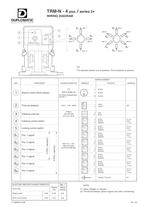
table.main {} tr.row {} td.cell {} div.block {} div.paragraph {} .font0 { font:5.00pt "Arial", sans-serif; } .font1 { font:7.00pt "Arial", sans-serif; } .font2 { font:8.00pt "Arial", sans-serif; } .font3 { font:10.00pt "Arial", sans-serif; } .font4 { font:11.00pt "Arial", sans-serif; } .font5 { font:13.00pt "Arial", sans-serif; } .font6 { font:15.00pt "Arial", sans-serif; } .font7 { font:17.00pt "Arial", sans-serif; } .font8 { font:19.00pt "Arial", sans-serif; } .font9 { font:22.00pt "Arial", sans-serif; } .font10 { font:28.00pt "Arial", sans-serif; } .font11 { font:14.00pt "Georgia",...
Open the catalog to page 14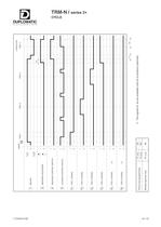
TRM-N / sries 2* CYCLE DUPLOMATIC I.T.6440-0109 A1-15
Open the catalog to page 15
TRM-N / sries 2* CYCLE DESCRIPTION DUPLOMATIC AUTOMATION 1. - Signais To get a change of positions on the TRM-N turrets, the control equipment (usually a N.C. equipment) must control the components mentioned below according to a well defined sequence (see wiring diagram on page 14). Motor (1) 镕 Indexing solenoid (3) The following signals from the turret are provided for the driving of the positioning cycle: - Angular position given by the proximity switch (61,62...) - Indexing control switch (4) - Locking control switch (5) 2. - Description of the operating sequence This description...
Open the catalog to page 16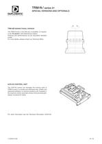
TRM-N / sries 2* SPECIAL VERSIONS AND OPTIONALS DUPLOMATIC AUTQMATIQN TRM-NB BIDIRECTIONAL VERSION The TRM-N turret, in the 200 size, is available, on request, in the "B version" with bidirectional rotation. Features and performances as per equivalent standard model. For more details, please contact our Technical Office. UCN-40 CONTROL UNIT The UCN-40 control unit manages the moving cycle of TRM-N turret in a simple and optimized way: simple and optimized software; no memory positions are occupied in the machine control; automatic chose of the shortest path; steady monitored for faults. For...
Open the catalog to page 18All Duplomatic Automation catalogs and technical brochures
-
TMY-BR (BA)
20 Pages
-
DM-TR* series
24 Pages
-
ELECTROSPINDLE
8 Pages
-
BME
4 Pages
-
BSV-N
20 Pages
-
SM(A)
24 Pages
-
DM
18 Pages
-
TRM-S
18 Pages
-
SM-BR
30 Pages
-
MDT
22 Pages
-
ODT-N
24 Pages


