- Catalogs
- Duplomatic Automation
- TMY-BR (BA)
TMY-BR (BA)
1 /20Pages

TMY-BR (BA)
1 /20Pages
Catalog excerpts

TURN-MILL TURRET WITH Y-AXIS TECHNICAL INFORMATION The data given in the I.T. are subject to technical modifications without notice.
Open the catalog to page 1
TMY-B* / series 11 MAIN FEATURES • High stiffness and accuracy thanks to the structure configuration and to slideway sizing. • Original clamping system (Patented) allowing the maximum rigidity for turning operations. • High strokes. • Modular concept, with standard turrets, for a cost-effective solutions. • Front and back-machining. COMPLETE RANGE • SM-BR radial driven tool turret. • SM-BA axial driven tool turret. Whit SM-BR turret and radial disc for front and back-machining Whit SM-BA turret and axial disc for front machining
Open the catalog to page 2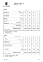
TMY-B* / series 11 TECHNICAL DATA Pitch of ball screw Gear transmission Working stroke FANUC AC spindle motor FANUC AC spindle motor Position accuracy Hydraulic brake on slides Motor encoder Linear encoder (optional) pressure Pmax (2) clamping force (in "Y" direction) Motor (with brake) (3) (1) SM-B 12 turret is fitted on "Y" axis 16 size. * (2) For friction factor 0,13. (3) Other motors on request. Turret (4) SM-BA or SM-BR Size N° Positions Tooling system Transportable inertia Positioning times Unclamping / Clamping times Hydraulic supply pressure Tool drive : • Toolholder coupling Motor (without...
Open the catalog to page 3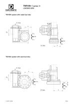
TMY-B* / series 11 LOADING DATA TMY-BR system with radial tool disc TMY-BA system with axial tool disc
Open the catalog to page 4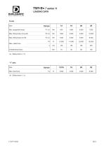
TMY-B* / series 11 LOADING DATA Turret Size Max. tilting torque (to push) Max. tilting torque (to lift) F4 Max. radial force a Unbalancing torque (4) Safety factor ≥ 1,3. “Y” axis Size Max. feed force
Open the catalog to page 5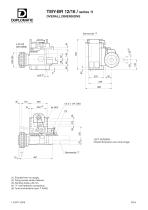
TMY-BR 12/16 / series 11 OVERALL DIMENSIONS LEFT VERSION: Overall dimensions are mirror-image (1) Ecluded from our supply. (2) Fixing screws center distance. (3) Working stroke ±40 mm. (4) "Y" axis hydraulic connections. (5) Turret connections (see I.T. 6445).
Open the catalog to page 6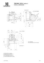
TMY-BA 12/16 / series 11 OVERALL DIMENSIONS LEFT VERSION: Overall dimensions are mirror-image (1) Ecluded from our supply. (2) Fixing screws center distance. (3) Working stroke ±40 mm. (4) "Y" axis hydraulic connections. (5) Turret connections (see I.T. 6445).
Open the catalog to page 7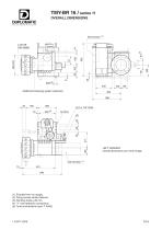
TMY-BR 16 / series 11 OVERALL DIMENSIONS 220 Additional clamping system (optional) LEFT VERSION: Overall dimensions are mirror-image (1) Ecluded from our supply. (2) Fixing screws center distance. (3) Working stroke ±40 mm. (4) "Y" axis hydraulic connections. (5) Turret connections (see I.T. 6445).
Open the catalog to page 8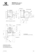
TMY-BA 16 / series 11 OVERALL DIMENSIONS 220 Additional clamping system (optional) LEFT VERSION: Overall dimensions are mirror-image (1) Ecluded from our supply. (2) Fixing screws center distance. (3) Working stroke ±40 mm. (4) "Y" axis hydraulic connections. (5) Turret connections (see I.T. 6445).
Open the catalog to page 9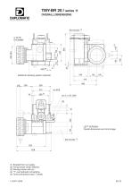
TMY-BR 20 / series 11 OVERALL DIMENSIONS Additional clamping system (optional) LEFT VERSION: Overall dimensions are mirror-image (1) Ecluded from our supply. (2) Fixing screws center distance. (3) Working stroke ±60 mm. (4) "Y" axis hydraulic connections. (5) Turret connections (see I.T. 6445). I.T.6471-0309
Open the catalog to page 10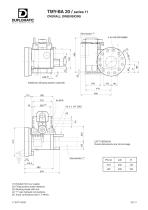
TMY-BA 20 / series 11 OVERALL DIMENSIONS Additional clamping system (optional) LEFT VERSION: Overall dimensions are mirror-image (1) Ecluded from our supply. (2) Fixing screws center distance. (3) Working stroke ±60 mm. (4) "Y" axis hydraulic connections. (5) Turret connections (see I.T. 6445). I.T.6471-0309
Open the catalog to page 11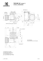
TMY-BR 25 / series 11 OVERALL DIMENSIONS Additional clamping system (optional) LEFT VERSION: Overall dimensions are mirror-image (1) Ecluded from our supply. (2) Fixing screws center distance. (3) Working stroke ±70 mm. (4) "Y" axis hydraulic connections. (5) Turret connections (see I.T. 6445).
Open the catalog to page 12
TMY-BA 25 / series 11 OVERALL DIMENSIONS Additional clamping system (optional) LEFT VERSION: Overall dimensions are mirror-image (1) Ecluded from our supply. (2) Fixing screws center distance. (3) Working stroke ±70 mm. (4) "Y" axis hydraulic connections. (5) Turret connections (see I.T. 6445).
Open the catalog to page 13
TMY-B* / series 11 WIRING DIAGRAM “Linear encoder” application (optional) Terminal board Electrical connection PG 7 “Limit switches” application (optional) Terminal board Electrical connection PG 13,5
Open the catalog to page 14
TMY-B* / series 11 WIRING DIAGRAM See data sheet of selected motor INCREMENTAL PULSE CODER See data sheet of selected motor See data sheet of selected motor 1 See data sheet of selected motor Y-AXIS ZERO SWITCH Y-AXIS CLAMPING VALVE EV2 sol-a See data sheet of selected valve See data sheet of selected component OPTIONAL LINEAR ENCODER EUCHNER ES 502 E See relevant data sheet COMMON NC NO COMMON COMMON NC NO COMMON INCREMENTAL PULSE CODER ZERO POINT Y-AXIS ZERO SWITCH PRESSURE SWITCH 1 0 Y-AXIS ZERO SETTING Y-AXIS MOVEMENT Y-AXIS CLAMPED (TURNING OPERATIONS) A The distance between coder marker...
Open the catalog to page 15
HYDRAULIC CONNECTIONS Needed instant flow Clamping turret DN recommended nominal diameter for hydraulic line Unclamping turret
Open the catalog to page 16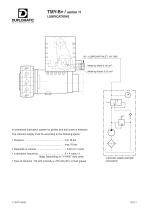
TMY-B* / series 11 LUBRICATIONS Metering Valve 0,10 cm3 Metering Valves 0,15 cm3 Lubricant supply example (escluded)
Open the catalog to page 17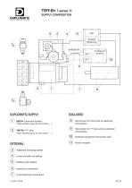
TMY-B* / series 11 SUPPLY COMPOSITION HYDRAULIC SUPPLY DUPLOMATIC SUPPLY Servomotor for Turret and its electrical connections Servomotor for "Y" Axis and its electrical connections Hydraulic equipment and power pack Power modules SM-B Turret with tooldisc Additional clamping system Linear encoder pre setting Rotating tool-holders Hydraulic connections Turret electrical connections
Open the catalog to page 18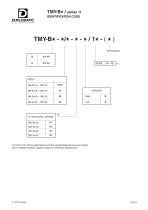
TMY-B* / series 11 IDENTIFICATION CODE "Y" AXIS TOTAL STROKE TMY-B 12 * TMY-B 16 * TMY-B 20 * TMY-B 25 * (1) From 10 to 19 the performance and the overall dimensions do not change. (2) For different strokes, please contact our Technical Department.
Open the catalog to page 19
e-mail: [email protected] come visit Duplomatic homepage:
Open the catalog to page 20All Duplomatic Automation catalogs and technical brochures


- Chuck
- Milling chuck
- Machining tool holder
- Milling tool holder
- Collet tool holder
- Rotary indexing table
- Tapping holder
- Horizontal rotary indexing table
- Machine tool rotary indexing table
- VDI chuck
- VDI tool holder
- CAPTO chuck
- BMT tool holder
- Disc tool turret
- Machining center tool holder
- CAPTO tool holder
- Hydraulic tool turret
- Direct-drive rotary indexing table
- Servo-driven tool turret