
Catalog excerpts

DUPLOMATIC AUTO M AT I O N SM-B* sries 30 ONE ONLY SERVOMOTOR TURN-MILL TURRETS TECHNICAL INFORMATION I.T. 6445 ISSUED 07-09 The data given in the I.T. are subject to technical modifications without notice.
Open the catalog to page 1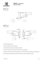
SM-B * / sries 30 MAIN FEATURES DUPLOMATIC automation SM-BA * /30 AXIAL VERSION ilnlnlnlnlrr JUUU SM-BR * /30 RADIAL VERSION **** -uuup 1 Super fast indexing times. 镕 Very high rigidity and loading capacity. Clamping/Unclampig system hydraulically operated. Օ One only servomotor drives the turret rotation and the rotating tools. All the disc stations can be used for rotating tools and only the working tool is driven without dead times. Օ Pressurizing air and centralized lubrication functions for driven tool system's long life. I.T.6445-0709 D1-2
Open the catalog to page 2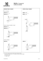
SM-B * / sries 30 COMPLETE RANGE DUPLOMATIC autqmatiqn (1) "C" or "F" identify the turret versions with compact housing. According to the turret sizes, it is available a double centerline height: "C" standard height. "F" bigger height. I.T.6445-0709 D1-3
Open the catalog to page 3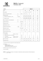
table.main {} tr.row {} td.cell {} div.block {} div.paragraph {} .font0 { font:6.00pt "Arial", sans-serif; } .font1 { font:7.00pt "Arial", sans-serif; } .font2 { font:8.00pt "Arial", sans-serif; } .font3 { font:11.00pt "Arial", sans-serif; } .font4 { font:14.00pt "Arial", sans-serif; } .font5 { font:17.00pt "Arial", sans-serif; } .font6 { font:46.00pt "Arial", sans-serif; } M SM-B * / sries 30 TECHNICAL DATA DUPLOMATIC automation Turret SM-B * Sizes 12 16 20 25 Tool stations 12 16 (4) 12 16 (4) 12 12 Inertia of transportable masses (1) Kgm 2 1,25 2,2 2,5 5,0 10 Positionina times: (2) 0,12...
Open the catalog to page 4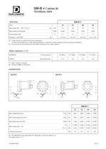
SM-B * / sries 30 TECHNICAL DATA DUPLOMATIC autqmatiqn Tool drive SM-B * Size 12 16 20 25 Max torque [S3 - 40% 10 min.] (5) Nm 14 28 40 66 Max speed at the spindle RPM 6.000 5.000 4.000 3.000 Transmission ratio t 1:1 1:1 1:1 1:1 Coupling DIN 5480 (6) 14 x 0,8 16 x 0,8 20 x 0,8 24 x 1,25 (5) These values are valid for free-shock oprations. In case of interrupted-cut or other shock-operations, a reduction of these values up to 50% must be considered. (6) Use only driven tool-holders with DIN 5480 coupling and zero detent system. Motor (optional) (7) (8) SIEMENS AC servomotor 1FT 6064 ... 1FT...
Open the catalog to page 5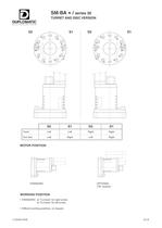
SM-BA * / sries 30 TURRET AND DISC VERSION DUPLOMATIC AUTOMATION S2 S1 D2 D1 S2 S1 D2 D1 Turret Left Left Right Right Tool d i sc Left Right Left Right MOTOR POSITION B B STANDARD OPTIONAL ("W" version) WORKING POSITION STANDARD: at "3 o'clock" for right turrets. at "9 o'clock" for left turrets. 镕 Different working positions, on request. I.T.6445-0709 D1-8
Open the catalog to page 8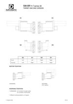
SM-BR * / sries 30 TURRET AND DISC VERSION DUPLOMATIC AUTO m ATI ON S1 D1 4*r S2 <3 D2 S2 S1 D2 D1 Turret Left Left Right Right Tool dise Left Right Left Right MOTOR POSITION STANDARD OPTIONAL ("W" version) WORKING POSITION STANDARD: at "3 o'clock" for right turrets. at "9 o'clock" for left turrets. 镕 Different working positions, on request. I.T.6445-0709 D1-9
Open the catalog to page 9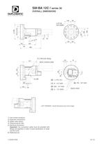
SM-BA 12C / sries 30 OVERALL DIMENSIONS DUPLOMATIC AUTQMATION 149 68 (6)- 0 25 H6 DIN 69880 0 15 g6 58|,J^ 261 26 465 LEFT VERSION: overall dimensions are mirror-image 1) Inlet coolant positions. 2) Hydraulic connections. 3) Safety valve (drain). 4) Pressurizing air inlet. 5) Electrical connection. Important: the connection cable must be provided with fittings and gaskets in order to avoid penetration of water into the turret. 6) Reference pin. I.T.6445-0709 D1-10
Open the catalog to page 10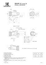
SM-BR 12 / sries 30 OVERALL DIMENSIONS DUPLOMATIC ,96, 149 68 0 d H6 DIN 69880 0 8 I_1 1> ,l, ,l, ,l, ,l, ,l, - m T oo (7) 0 15 g6 46 ,92, 261 30 413 503 (5) PN - 1/8" GAS N°2 M10 (for lifting) Motor interface group 91 0 2 8 5 (3) H - 1/8" GAS (6) 1 x PG 13,5 (1) R - 1/4" GAS (2) A-B - 1/4" GAS (4) (L - 1/8" GAS) _ 28 i tp- us- -vt -w- -vt 1 -鈗 - rh rk fk"y"fk fk LEFT VERSION: overall dimensions are mirror-image 1) Inlet coolant positions. 2) Hydraulic connections. 3) Centralized lubrication inlet. 4) Safety valve (drain). 5) Pressurizing air inlet. 6) Electrical connection. Important: the...
Open the catalog to page 11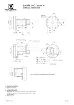
SM-BA 16C / sries 30 OVERALL DIMENSIONS DUPLOMATIC autqmation 82 o 5 30. 0 30 H6_ DIN 69880 0 m r ---r m ^ f~ L_|_J J 162 .102. 176 0 ~=r ° ooCM + O o CM 0 17 g6 ---- ------- U6) h»" 28 67 401. 180 m 97 439 1) Inletcoolant positions. 2) Hydraulic connections. 3) Safety valve (drain). 4) Pressurizing air inlet. 5) Electrical connection. Important: the connection cable must be provided with fittings and gaskets in order to avoid penetration of water into the turret. 6) Reference pin. I.T. 6445-0709 D1-12
Open the catalog to page 12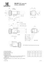
SM-BR 16 / sries 30 OVERALL DIMENSIONS DUPLOMATIC automation 67 0 d H6 DIN 69880 176 82 1, < _ (7) B 0 17 g6 162 102 109 105 185 548 (5) PN - 1/4" GAS N° 2 M10 (for lifting) Motor interface group 111 34 (3) H - 1/8" GAS _ (6) 1 x PG 13,5 _ (4) (L - 1/8" GAS) (2) A/B - 1/4" GAS (1) R - 1/4" GAS 1 LEFT VERSION: Overall dimensions are mirror-image uuuuuu 1) Inlet coolant positions. 2) Hydraulic connections. 3) Centralized lubrication inlet. 4) Safety valve (drain). 5) Pressurizing air inlet. 6) Electrical connection. Important: the connection cable must be provided with fittings and gaskets in...
Open the catalog to page 13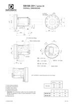
SM-BA 20* / sries 30 OVERALL DIMENSIONS DUPLOMATIC autqmation 0 40 H6 DIN 69880 100 < a d cl 0 20 g6 (6) 0 3 ^ 200 L ^ 75 21 243 35 429 N° 2 M10 (for lifting) 133 40 (5) 1 x PG 13,5 (3) L - (1/4" GAS) (2) A/B - 3/8" GAS (1 ) R - 3/8" GAS _ 5 8 M 9 9 (4) PN - 1/8" GAS BACK VIEW LEFT VERSION: overall dimensions are mirror-image 1) Inlet coolant positions. 2) Hydraulic connections. 3) Safety valve (drain). 4) Pressurizing air inlet. 5) Electrical connection. Important: the connection cable must be provided with fittings and gaskets in order to avoid penetration of water into the turret....
Open the catalog to page 14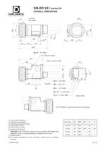
SM-BR 20 / sries 30 OVERALL DIMENSIONS DUPLOMATIC automation C 0 40 H6 DIN 69880 100 < + + + + + + + CM 0 5 2 J_I_I_I_L . (7)-134 215 0 20 g6 en 0 3 _i B 132 628 (5) PN - 1/4" GAS N° 2 M10 (for lifting) Motor interface plate (3) H - 1/8" GAS l_ \for M12 (6) 1 x PG 13,5 133 40 (4) L - (1/4" GAS) (2) A/B - 2 x 3/8" GAS (1 ) R - 1 x 3/8" GAS _ BACK VIEW 0f LEFT VERSION: overall dimensions are mirror-image 0 1) Inlet coolant positions. 2) Hydraulic connections. 3) Centralized lubrication inlet. 4) Safety valve (drain). 5) Pressurizing air inlet. 6) Electrical connection. Important: the...
Open the catalog to page 15All Duplomatic Automation catalogs and technical brochures
-
TMY-BR (BA)
20 Pages
-
DM-TR* series
24 Pages
-
ELECTROSPINDLE
8 Pages
-
BME
4 Pages
-
BSV-N
20 Pages
-
SM(A)
24 Pages
-
DM
18 Pages
-
TRM-S
18 Pages
-
TRM-N
20 Pages
-
MDT
22 Pages
-
ODT-N
24 Pages


