
Catalog excerpts

DUPLOMATIC AUTO M ATI ON ODT-N * sries 50 MODULAR DRIVEN TOOL DEVICE FOR AXIAL SYSTEM DIN 1809 COUPLING TECHNICAL INFORMATION The data grven in tne IX are subject (o lectirtcal rrcomcaDcna wfthoU noOO.
Open the catalog to page 1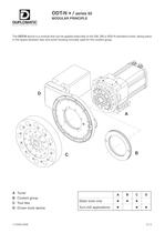
10; 80 ODT-N */ sries 50 MODULAR PRINCIPLE DUPLOMATIC AUTOMATiDN The ODT-N devlce is a module tha can be applied externally lo the DM, SM or BSV-N standard turrets. taking place in the space between dise and turret housing normally used tor the coolant group. A Turret B Coolant group C Tool dise D Driven tools device - A B C D Static tools onty 鯕 Օ Turn-mill applications Օ IT6482-0609 C1-2
Open the catalog to page 2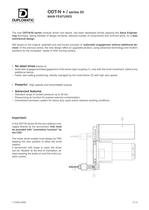
ODT-N */ sries 50 MAIN FEATURES DUPLOMATIC AJTQMATiON The new ODT-N/50 sries modular drrven tool device, has been developed strictly applyjng the Value Enginee驭ring technique, taking benefrts ot design similarit reduced number ot components and common parts, for a lean mechanical ctesign Still based on the original, patented and well known prindple ot Automatic engagement wilhoul additionaf de-vicosT ot the previous sries, the new design offers an upgraded product using advanced technology and modem solutions (or the increased needs ot CNC turning centers. 驕 No dead times thanks to:...
Open the catalog to page 3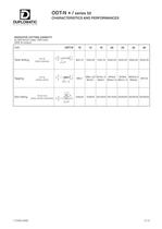
ODT-N */sries 50 CHARACTERISTICS AND PERFORMANCES DUPLOMATIC AJTQM AT i O N INDICATIVE CUTTING CAPACITY lor 600 Wmm2 steel. HSS tools (Wrth fit motors) SIZE ODT-N 10 12 16 20 25 32 40 Twist drilling d闕 d a 8x0,15 10x0.20 14x0,15 20x0^0 22x0,20 30x0,20 32x0,25 TaPPin9 in^Mmm) -a-1 d d*JL-P P ** M ■-' ■ ' M6X1.25 M12x1 M10x1.5 M24xl M16x2 M 24x1,5 M18x2 M27x1,5 M22X2.5 M33x2 M27x3 Slot milling [mn) ^^^^ 10x6x45 12x8x45 20x10x40 25x14x40 25x20x40 40x20x35 40x30x35 I.T.6482-0609 C1-5
Open the catalog to page 5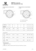
table.main {} tr.row {} td.cell {} div.block {} div.paragraph {} .font0 { font:12.00pt "Arial", sans-serif; } .font1 { font:13.00pt "Arial", sans-serif; } .font2 { font:14.00pt "Arial", sans-serif; } .font3 { font:15.00pt "Arial", sans-serif; } .font4 { font:16.50pt "Arial", sans-serif; } .font5 { font:17.00pt "Arial", sans-serif; } .font6 { font:18.00pt "Arial", sans-serif; } .font7 { font:26.00pt "Arial", sans-serif; } .font8 { font:31.00pt "Arial", sans-serif; } .font9 { font:38.00pt "Arial", sans-serif; } .font10 { font:64.00pt "Arial", sans-serif; } .font11 { font:30.00pt "Arial...
Open the catalog to page 6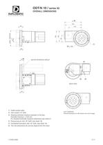
ODT-N 10/sries 50 OVERALL DIMENSIONS DUPLOMATIC AJTQMATiON (6) 210 170 I ] J 飮 __ il MOTOR INTERFACE GROUP & 2 SACKVIEW 1) Outlet coolant valve. 2) Intet coolant 1/4'GAS. 3) Rotating tooibolder locations diameter on the clsc+ Diameter tolrance: ± 0,02 mm. For standard toolholder locations dimensions see sfteet 21 4) Pressunzing alrirtet 1/8" GA& (see sheet 18). 5) CentraJized lubrlcation Inlet W GAS. (see sheet 19). 6) The max dimensions (E) and (G) dpend from the motor. _EFT VERSION: Dvofali 0m©n$K>ns w lofl v驴r&on ara mlrfor I.T.6482-0609 C1-7
Open the catalog to page 7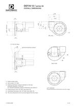
ODT-N 12/sries 50 OVERALL DIMENSIONS DUPLOMATIC AJTQMATi ON s; il ■ * i o i «1- _ t_! [3) 0 240 N:1 MlCtorlrtng) For standard toolholder locations dimensions see sheet 21 l_ept version 4) Pressunzlngairinlet 1/6* GAS. (see sheet 18)* Owi dimensions forleft version ace miror triage 5) Centrallzed lubncatJon inlet 1/8' G AS. (see sheet 19). 6) The max dimensions (E) (F) and (G) d黩pend from the motor iT.6482-0609 C1-8
Open the catalog to page 8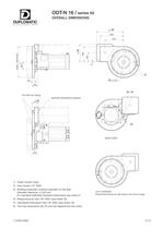
ODT-N 16 / sries 50 OVERALL DIMENSIONS DUPLOMATIC AUTQMATIQN E(6) 255 204 o 4 LL (3) 0 270 (1) o oo 26 1 58 (5) (4) N°2 M10 (for lifting) G(6) MOTOR INTERFACE GROUP BACK VIEW 1) Outlet coolant valve. 2) Inlet coolant 1/4" GAS. 3) Rotating toolholder locations diameter on the disc. Diameter tolerance: ± 0,02 mm. For standard toolholder locations dimensions see sheet 21. 4) Pressurizing air inlet 1/8" GAS. (see sheet 18). 5) Centralized lubrication inlet 1/8" GAS. (see sheet 19). 6) The max dimensions (E) (F) and (G) depend from the motor. LEFT VERSION: Overall dimensions for left version are...
Open the catalog to page 9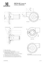
N°2 M10 (for lifting) G(6) MOTOR INTERFACE GROUP (4) (5) (2) BACK VIEW 1) Outlet coolant valve. 2) Inlet coolant with fitting for pipe 010. 3) Rotating toolholder locations diameter on the disc. Diameter tolerance: ± 0,02 mm. For standard toolholder locations dimensions see sheet 21. 4) Pressurizing air inlet 1/8" GAS. (see sheet 18). 5) Centralized lubrication inlet 1/8" GAS. (see sheet 19). 6) The max dimensions (E) and (G) depend from the motor. LEFT VERSION: Overall dimensions for left version are mirror image I.T.6482-0609 C1-10
Open the catalog to page 10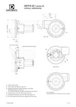
ODT-N 25/sries 50 overall dimensions DUPLOMATIC AJTQMATiON E(6) ■ yji j ■ |--- f_---- i 12 N*2 M12(for lifting) G (6) MOTOR INTERFACE GROUP 3ACK VIEW 1) Outlet cootent valve. 2) Inletcoolant witti fttling for pipe ©10. 3) Rotating toolholder locations diameter on the dsc. Diameter tol闩rance: ± 0.02 mm. For standard toolholder locations dimensions see sheet 21 4) Pressuhzing air irtet 1/8* G AS. (see sheet 18). 5) Centralized lubricatfon Inlet W GAS. (see sheet 19). 6) The max dimensions (E) and (G) dpend from the motor LEFT VERSION: Owrail dimensions for loft «reion are mirror imago...
Open the catalog to page 11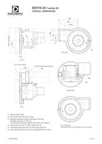
ODT-N 32 / sries 50 overall dimensions DUPLOMATIC AUTOMATi ON E(6) ! X/~ -----^ [phi i LM"-=1- ■■■ ■■■■ _______闯 3ACK VIEW 1) Outlet coolant valve, 2) Inlet coolant 3/8* G AS (turret side). 3) Rotang tooiholder locations diameter on the dise. Diameter tolrance: ± 0.02 mm. For standard toolholder locations dimensions see sheet 21. 4) Pressunzing air inlet 1/8" G AS. (see sheet 18), 5) Centralized lubricatfon inlet 1/6' G AS (see sheet 19). 6) The max dimensions (E) (F) and (G) d멩pend from Ihe motor LEFT VERSION: OveraH dimensions tor le! version are mirror imara iT.6482-0609 C1-12
Open the catalog to page 12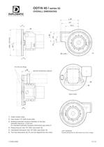
ODT-N 40/sries 50 overall dimensions DUPLOMATIC AJTQMATiON E(6) 1闗 * 1 t 1 j_1 (ח - [3) o 580 SJ»2 M12 (for ifing) G<6) MOTOR INTERFACE GROUP 3ACK VIEW 1) Outlet cootant valve. 2) lntetcoolant1/2*GAS(turretside). 3) Rotating toolholder locations diameter on the dsc. Diameter tolrance: ± 0.02 mm. For standard toolholder locations dimensions see sheet 21 4) Pressuhzing air irtet 1/8* G AS. (see sheet 18). 5) Centralized lubrlcation Inlet W GAS. (see sheet 19). 6) The max dimensions (E) (F) and (G) dpend from the motor LE FT VERSION: Overall dimensions for ieft version are mirror image...
Open the catalog to page 13All Duplomatic Automation catalogs and technical brochures
-
TMY-BR (BA)
20 Pages
-
DM-TR* series
24 Pages
-
ELECTROSPINDLE
8 Pages
-
BME
4 Pages
-
BSV-N
20 Pages
-
SM(A)
24 Pages
-
DM
18 Pages
-
TRM-S
18 Pages
-
TRM-N
20 Pages
-
SM-BR
30 Pages
-
MDT
22 Pages


