- Catalogs
- Duplomatic Automation
- DM-TR* series
DM-TR* series
1 /24Pages

DM-TR* series
1 /24Pages
Catalog excerpts

RADIAL DRIVEN TOOL SYSTEM WITH DIRECT MOTOR TURRETS TECHNICAL INFORMATION The data given in the IT. are subject to technical modifications without notice.
Open the catalog to page 1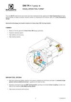
RADIAL DRIVEN TOOL TURRET The new DM-TR radial driven tool turrets have been developed strictly applying the Value Engineering technique, taking benefits of design similarity, reduced number of components and common parts, for a lean mechanical design. Advanced technology and modern solution for heavy duty CNC Turning Centers. TURRET • Based on the last generation ; 180 Drive DM design (patented). 10 Direct • Hydraulic clamping system. • High stiffness and accuracy. • High loading capacity. DRIVEN TOOL SYSTEM • New lean mechanical design, based on the original, patented and well known principle...
Open the catalog to page 3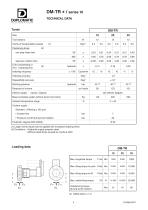
DM-TR * / series 10 TECHNICAL DATA Turret Tool stations one step index time step-less rotation time (Tsb) Unclamping or (Tb) Clamping time Positioning times: Inertia of transportable masses Indexing frequency Indexing accuracy Repeatibility accuracy Working pressure Electric supply - Inputs / Outputs Mass (complete system without driven tool motor) Ambient temperature range • Costant flow • Pressure cut-off during turret rotation Coolant supply : Standard : (Filtering ≤ 100 µm) (1) Larger inertia values can be applied with increased indexing times (2) Conditions: • Hydraulic supply properly sized....
Open the catalog to page 4
DM-TR* / series 10 TECHNICAL DATA Tool drive Transmission ratio Coupling (4) These values are valid for free-shock operations. In case of interrupted-cut or other shock-operations, a reduction of these values up to 50% must be considered. Size Siemens A.C. Motor — Max speed Fanuc A.C. Servomotor — Torque — Max speed Fanuc A.C. Spindle motor — Torque (5) Servomotor with "orientation function" by CNC must be used. (6) Other motors on request. INDICATIVE CUTTING CAPACITY for 600 N/mm2 steel, HSS tools (With fit motors) Twist drilling Slot milling
Open the catalog to page 5
SIZES AND TOOLING LAY-OUT NEW BMT TOOLING SYSTEM • Size range from 45 to 75. • 4 bolts fitting system to maximize cutting rigidity. • 2 keys and centering diameter reference system to reach the best positioning accuracy. • Oversize tenon coupling to grant high torque and power transmission. Disc size Indicative tool swing Matching DM-TR turret size
Open the catalog to page 6
SIZES AND TOOLING LAY-OUT DIN 69880 traditional TOOLING SYSTEM • Size range from 25 to 50. • Tenon coupling DIN 1809. • Same rotating toolholders of axial ODT-N driven tool system. Disc size Indicative tool swing Matching DM-TR turret size
Open the catalog to page 7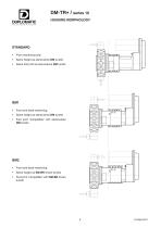
HOUSING MORPHOLOGY STANDARD • Front machining only • Same height as stand-alone DM turrets • Same foot print as stand-alone DM turrets BM1 • Front and back-machining • Same height as stand-alone DM turrets • Foot print "compatible" with stand-alone DM turrets BM2 • Front and back-machining • Same height as SM-BR driven turrets • Foot print "compatible" with SM-BR driven turrets
Open the catalog to page 8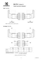
TURRET AND DISC VERSIONS BMT TOOLING LEFT TURRET RIGHT TURRET NOTE: The BMT tool disc is always the same. Tool disc WORKING POSITION: • STANDARD: at "3 o'clock" for right turrets. at "9 o'clock" for left turrets. • Different working positions, on request.
Open the catalog to page 9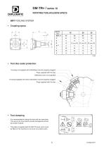
ROTATING TOOLHOLDERS SPECS BMT TOOLING SYSTEM • Coupling specs L DM-TR size • Tool disc seats protection Housing not engaged with toolholders must be properly plugged: Plugs supplied with the disc Additional cover (not supplied) Housing engaged with static toolholders must be properly plugged: Plugs supplied with the disc • Tool clamping – It is recommended to clamp the tools with two wrenches. The use of one only wrench causes damages the driven tool center module. – This plate is supplied with the DM-TR turret, and it must be fitted on the machine so as to be very clearly seen.
Open the catalog to page 10
ROTATING TOOLHOLDERS SPECS DIN 69880 TOOLING SYSTEM • Coupling specs DIN 1809 C DM-TR size • Angular adjusting pins on disc (for radial rotating units) • Tool clamping – It is recommended to clamp the tools with two wrenches. The use of one only wrench causes damages the driven tool center module. – This plate is supplied with the DM-TR turret, and it must be fitted on the machine so as to be very clearly seen. – Housing not engaged with toolholders must be properly plugged (DIN 69880 Shape Z2).
Open the catalog to page 11
MAIN OVERALL DIMENSIONS FRONT Machining only B U LEFT VERSION: overall dimensions are mirror-image DM-TR SIZE TOOL DISC DM-TR SIZE 2) Hydraulic connections. 3) Centralized lubrication inlet. 4) Safety valve. 5) Electrical connectors. 6) Reference pin.
Open the catalog to page 12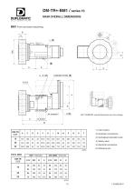
DM-TR*-BM1 / series 10 MAIN OVERALL DIMENSIONS LEFT VERSION: overall dimensions are mirror-image DM-TR SIZE TOOL DISC DM-TR SIZE 2) Hydraulic connections. 3) Centralized lubrication inlet. 4) Safety valve. 5) Electrical connectors. 6) Reference pin.
Open the catalog to page 13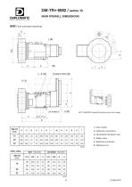
DM-TR*-BM2 / series 10 MAIN OVERALL DIMENSIONS LEFT VERSION: overall dimensions are mirror-image DM-TR SIZE TOOL DISC DM-TR SIZE 2) Hydraulic connections. 3) Centralized lubrication inlet. 4) Safety valve. 5) Electrical connectors. 6) Reference pin.
Open the catalog to page 14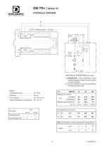
DM-TR* / series 10 HYDRAULIC DIAGRAM HYDRAULIC POWER PACK (Example) (1) IMPORTANT: A flow adjustment valve must be foreseen in order to avoid a violent or noisy clamping. (2) The accumulator's volume is according to the real pump flow rate. Needed instant flow [l/m] Clamping turret Unclamping turret DN recommended nominal diameter for hydraulic line ≤6m
Open the catalog to page 15
CENTRALIZED LUBRICATION SYSTEM The DM-TR turret has been preset with a lubrication function, that can be used in order to prevent wearing increasing due to heavy driven tool duty cycle. Metering valve (not supplied) Lubrication drain – Lubrication supply: • Type of lubricant : Oil with viscosity ≤ 750 cSt (40°) or fluid grease. WARNING: If oil contamination inside the working area is not allowed, please contact our Technical Dept.
Open the catalog to page 16All Duplomatic Automation catalogs and technical brochures


- Chuck
- Milling chuck
- Machining tool holder
- Milling tool holder
- Collet tool holder
- Rotary indexing table
- Tapping holder
- Horizontal rotary indexing table
- Machine tool rotary indexing table
- VDI chuck
- VDI tool holder
- CAPTO chuck
- BMT tool holder
- Disc tool turret
- Machining center tool holder
- CAPTO tool holder
- Hydraulic tool turret
- Direct-drive rotary indexing table
- Servo-driven tool turret