
Catalog excerpts

DUPLOMATIC AUTO M ATI O N BSV-N sries 25 ELECTROMECHANICAL TURRETS TECHNICAL INFORMATION I.T. 6430 09-08 The data given in the I.T. are subject to technical modifications without notice.
Open the catalog to page 1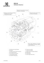
BSV-N WORKING PRINCIPLE DUPLOMATIC P Main overall dimensions and fixings interchangeable with previous BSV-N sries and SM turrets. A) Electrical motor (three-phase) B) Gearbox C) Rotation and cam locking mechanism D) Pre-indexing solenoid E) Pre-indexing control switch F) Shock-absorber system G) Preloaded locking spring H) 3-parts front coupling I ) Locking control switch L) Angular position transmitter (absolute) M) Rotating plate N) Coolant flange P) Quick change coolant valve I.T.6430-0908 B1-2
Open the catalog to page 2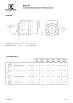
Repeatibility accuracy oc = ± 1,6" ( 0,78 um/100 mm) Indexing accuracy p = ± 4" ( 1,9 um/100 mm) Loading capacity BSV-N 120 BSV-N 160 BSV-N 200 BSV-N 250 BSV-N 320 BSV-N 400 ^^^^|F1 Max. tangential torque F1xb Nm 750 1.600 3.500 6.000 12.000 24.000 -P" Max. tilting torque (to push) F2xb F* Nm 850 1.900 5.200 10.000 16.000 32.000 b---'חJ" Max. tilting torque (to lift) F3xb '-* F3 Nm 400 800 2.500 4.000 7.000 15.000 b f (q)*\P Unbalancing torque P x b Nm 10 12 40 60 120 400 I.T.6430-0908 B1-4
Open the catalog to page 4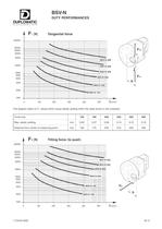
Microsoft Word - DG600 GPRS brochure.doc table.main {} tr.row {} td.cell {} div.block {} div.paragraph {} .font0 { font:10.00pt "Times New Roman", serif; } BSV-N DUTY PERFORMANCES DUPLOMATIC AUTOMATION i Fi [N] Tangential force 200000 100000 80000 60000 40000 20000 10000 8000 6000 4000 2000 1000 0 100 200 300 400 500 b [mm] The diagram refers to Fi values which cause elastic yelding within the rates shown in the schedule. Turret size 120 160 200 250 320 400 Max. elastic yelding mm 0,05 0,07 0,08 0,14 0,12 0,16 Distance from centre of measuring point mm 140 170 220 270 330 350 F2 [N] Tilting...
Open the catalog to page 5
BSV-N PARAMETERS FOR TURRET SELECTION DUPLOMATIC S: CHIP CROSS-SECTION (max) for steel R = 600 N/mm2 Ks = 2.200 N/mm2 N: POWER (max) for Vt = 200 m/min N i [kW] 4 S [mm2] 300 150 100 50 40 30 20 10 100 80 60 40 BSV-N 400 r _ -1 te- |||r MUI| - u BSV-N 320 : BSV-N 250 20 10 8 6 b BSV-N 160 4 2 5 1 0,8 0,6 0,5 0 100 200 300 400 500 b [mm] ĕ For any material with diffrent Ks: Sx = S X 2.200 Kx For different cutting speeds: Nx = N X Vtx 200 I.T.6430-0908 B1-7
Open the catalog to page 7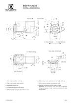
BSV-N 120/25 OVERALL DIMENSIONS DUPLOMATIC AUTOMATION N°1 M12 (for lifting) TOOL DISC INTERFACE (3) ^1 cm 0~ 10 m CD 11 II (7) OR 2050 E 0,8/ 2 2 70 11\ for M8 08 010 030 Js6 016 50 30 30 30 jmin ^ 080 max 085 1) Inlet coolant position, at choise. 2) Right or left coolant outlet position. 3) Adjustable coolant ring. 4) Coolant outlet displacement range. 5) Soft surface for boring the disc reference pins. 6) Reference pin to be positioned on both side, at choise. 7) Reference pins between tool disc and turret. 8) Electrical connections on both side, at choise. Important: The connection cable...
Open the catalog to page 8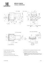
BSV-N 160/25 OVERALL DIMENSIONS DUPLOMATIC AUTQMATIQN TOOL DISC INTERFACE 1) Inlet coolant position, at choise. 2) Right or left coolant outlet position. 3) Adjustable coolant ring. 4) Coolant outlet displacement range. 5) Soft surface for boring the disc reference pins. 6) Reference pin to be positioned on both side, at choise. 7) Reference pins between tool disc and turret. 8) Electrical connections on both side, at choise. Important: The connection cable must be provided with fittings and gaskets in order to avoid penetration of water into the turret. I.T.6430-0908 B1-9
Open the catalog to page 9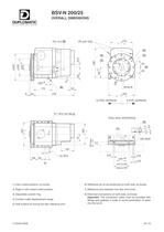
BSV-N 200/25 OVERALL DIMENSIONS DUPLOMATIC AUTQMATION N°1 M12 (for lifting) o CM CM TOOL DISC INTERFACE (3) X E 0,8/ in 2 30 min 0130 ■-1-1 max 0140 1) Inlet coolant position, at choise. 2) Right or left coolant outlet position. 3) Adjustable coolant ring. 4) Coolant outlet displacement range. 5) Soft surface for boring the disc reference pins. 6) Reference pin to be positioned on both side, at choise. 7) Reference pins between tool disc and turret. 8) Electrical connections on both side, at choise. Important: The connection cable must be provided with fittings and gaskets in order to avoid...
Open the catalog to page 10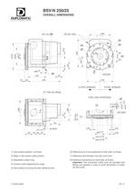
BSV-N 250/25 OVERALL DIMENSIONS DUPLOMATIC AUTQMATIQN PG 13,5(8) (1)3/8" GAS ^ i = _(3) -(2) 20° n 5 2 N 5 2 3 o S s cm o cm s cd s (4) 0~0 + LO CM _! Q 20° 1C SI 1 F» 026 g6 (6) 3/ M12x20 210 35 10 32 378 I 310 12 POS. VERSION 8 POS. VERSION H h N°1 M12 (for lifting) 0 8 2 TOOL DISC INTERFACE r(3) (7) 0 0= 2 ^ I 'OR 2050 cm f 20 X for M16 82 J 4^4^43^ max 0175 1) Inlet coolant position, at choise. 2) Right or left coolant outlet position. 3) Adjustable coolant ring. 4) Coolant outlet displacement range. 5) Soft surface for boring the disc reference pins. 6) Reference pin to be positioned...
Open the catalog to page 11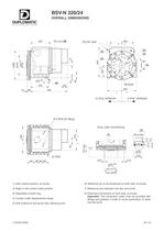
BSV-N 320/24 OVERALL DIMENSIONS DUPLOMATIC AUTQMATION N°2 M16 (for lifting) cm n 6 i^- 11 (M ---Ih TOOL DISC INTERFACE (7) a (3)- _OR 3106, ~ 0,2 025 0,8/ =, i ii 016 il .013 08OJs6 min 0170 ח-1-» 032 max 0220 1) Inlet coolant position, at choise. 2) Right or left coolant outlet position. 3) Adjustable coolant ring. 4) Coolant outlet displacement range. 5) Soft surface for boring the disc reference pins. 6) Reference pin to be positioned on both side, at choise. 7) Reference pins between tool disc and turret. 8) Electrical connections on both side, at choise. Important: The connection cable...
Open the catalog to page 12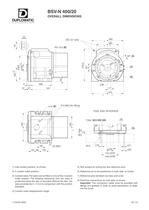
BSV-N 400/20 OVERALL DIMENSIONS DUPLOMATIC AUTQMATIQN 23 CD PG 13,5(8) (1)1/2" GAS 465 28° (4) l -(2) (5) o o cm 11 J |, , 308 _ 12^47^_541 J470 014(6) N°2 M24 (for lifting) TOOL DISC INTERFACE T-Nut M12 DIN 508 (7) 11 0,8/ -(3) 2 4 ^1 Mi 56 for M24 M12 / 016. il. 011 ^ 022 63 60 140 01OOJs6 min 0245 -1- max 0255 1) Inlet coolant position, at choise. 2) 4 coolant outlet position. 3) Coolant valve. The valve can be fitted on one of the 4 coolant outlet position. The drawing represents how the valve is positioned when the disc is mounted. Without the disc, the valve produtes by 2 ^ 3 mm is...
Open the catalog to page 13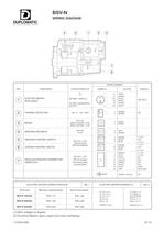
BSV-N WIRING DIAGRAM DUPLOMATIC © ® ® ® @ REF. COMPONENT ELECTRIC MOTOR (three-phase) © THERMAL DETECTOR © BRAKE © INDEXING SOLENOID © INDEXING CONTROL SWITCH © LOCKING CONTROL SWITCH © ANGULAR POSITION TRANSMITTER (ABSOLUTE) WIRING NUMBER SIGNALS CHARACTERISTICS SIMBOLS COLOUR (1) 220-380 V 50/60 Hz For other characteristics see Tab. 1 U1 WHITE V1 GREEN W1 BLACK U2 WHITE V2 GREEN W2 BLACK See Tab. 2 135 °C 1,5A 250V n. BROWN BROWN (2) 24 V D.C. BSV-N 120/160 = 8 W BSV-N 200/400 = 12 W GREEN GREEN 24V D.C. 44 W - 5 - 6 BLUE BROWN /"S - 7 - 8 - 9 BROWN BLACK BLUE + V D.C. EXIT 0 V D.C. <>/^...
Open the catalog to page 15All Duplomatic Automation catalogs and technical brochures
-
TMY-BR (BA)
20 Pages
-
DM-TR* series
24 Pages
-
ELECTROSPINDLE
8 Pages
-
BME
4 Pages
-
SM(A)
24 Pages
-
DM
18 Pages
-
TRM-S
18 Pages
-
TRM-N
20 Pages
-
SM-BR
30 Pages
-
MDT
22 Pages
-
ODT-N
24 Pages


