- Catalogs
- DST Dauermagnet-SystemTechnik GmbH
- Operating and assembly instructions
- Company
- Products
- Catalogs
- News & Trends
- Exhibitions
Operating and assembly instructions
1 /31Pages

Operating and assembly instructions
1 /31Pages
Catalog excerpts
fluid technology solutions Operating and assembly instructions Permanent magnetic couplings
Open the catalog to page 1
General . . . . . . . . . . . . . . . . . . . . . . . . . . . . . . . . . . . 4 Basic principles . . . . . . . . . . . . . . . . . . . . . . . . . . . . . . . . 4 Personnel qualification and training. . . . . . . . . . . . . . . . 4 Safety symbols. . . . . . . . . . . . . . . . . . . . . . . . . . . . . . . . . 4 Notes . . . . . . . . . . . . . . . . . . . . . . . . . . . . . . . . . . . . . 5 Permissible modes of operation . . . . . . . . . . . . . . . . . . . 5 Dangers arising from non-observance of the operating and assembly instructions . . . . . . . . . . 5 Safety awareness. . . . . . ....
Open the catalog to page 2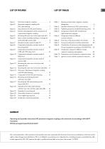
Figure 1: Figure 2: Figure 3: Figure 4: Figure 5: Figure 6: Figure 7: Figure 8: Figure 9: Figure 10: Figure 11: Figure 12: Figure 13: Figure 14: Figure 15: Figure 16: Figure 17: Figure 18: Figure 19: Figure 20: Figure 21: Figure 22: Table 1: Meaning of permanent magnetic coupling designation. . . . . . . . . . . . . . . . . . . . . . . . . . . . . . . . . . 6 Table 2: Standard clearance of SSiC plain bearing . . . . . . . . 7 Table 3: Tightening torque for standard fastening screws. . . 16 Table 4: Temperature limits for DST standard and high temperature magnets. . . . . . . . . . . . . . . ....
Open the catalog to page 3
1. GENERAL The basic advice given in these operating and assembly instructions on assembly/installation, operation and maintenance is a prerequisite for safe handling of the coupling and prevents damage to property and personal injury. The permanent magnetic coupling may only be used under the operating conditions listed in the referenced documents. All other operating conditions which are not listed in the technical documentation must be agreed with DST before commissioning. It is essential to comply with the safety instructions in these operating and assembly instructions. The operating and...
Open the catalog to page 4
All indications listed in this section imply a danger with a high degree of risk. In case of non-observance of the operating and assembly instructions and the listed safety instructions, any claim for warranty and compensation expires. 2.1 Permissible modes of operation The permanent magnetic coupling may only be used under the operating conditions specified in the applicable documents. The SSiC plain bearing (if used) must never be operated dry (without medium). The permanent magnetic coupling may only be operated when completely assembled and in a technically perfect condition. The permanent...
Open the catalog to page 5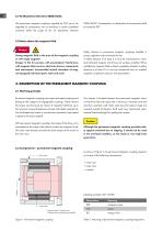
2.7 EC Machinery Directive 2006/42/EC The permanent magnetic couplings supplied by DST are to be regarded as components, not as machines or partly completed machines within the scope of the EC Machinery Directive 2006/42/EC. Consequently, no declaration of incorporation shall be issued by DST. 2.8 Notes about the magnetic field Danger Strong magnetic field in the area of the magnetic coupling or with single magnets! Danger to life for persons with pacemakers! Interference with magnetic data carriers, electronic devices, components and instruments! Uncontrolled mutual attraction of magnet-equipped...
Open the catalog to page 6
3.2.1 Extension by a SSiC plain bearing Outer rotor As shown in Figure 2, the permanent magnetic coupling with SSiC plain bearing consists of the following components SSiC plain bearing • inner rotor • outer rotor • canister • SSiC plain bearing The SSiC plain bearing is attached to the shaft of the output side by fitting a key connection. The inner rotor is bolted to the SSiC plain bearing. Inner rotor Pressure area in normal case (Pressure from outside also possible) Figure 2: Permanent magnetic coupling with SSiC plain bearing Axial clearance of SSiC plain bearing Figure 3: Gap clearance of...
Open the catalog to page 7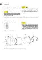
4. ASSEMBLY Before installation, check all individual parts/assemblies for completeness and all relevant dimensions for dimensional accuracy. During assembly, observe the weight of the components – it may be necessary to use lifting equipment. Caution Solid magnetic particles are not permitted in the area of the permanent magnetic coupling, as they can adhere to the outer rotor and / or inner rotor, which can cause the rotor to rub against the canister and thus lead to malfunctions! Assembly aids or tools as well as the permanent magnetic coupling components can be attracted by the magnetic field...
Open the catalog to page 8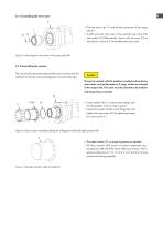
4.1.1 Assembling the inner rotor II • Push the inner rotor (1) onto the key connection of the output side (II) • A xially screw the inner rotor (1) by using the cap screw (VII) and washer (VI) [Alternatively: secure with set screw (7), as described in section 4.1.3 Assembling the outer rotor] Figure 5: Mounting the inner rotor to the output side (A1) 4.1.2 Assembling the canister The use of purely static seals separates the area in contact with the medium from the dry area and designates it as technically tight. The part in contact with the medium is sealed exclusively by static seals, such as...
Open the catalog to page 9
4.1.2.1 Assembling the canister made of borosilicate Figure 8: Components/assembly canisters made of borosilicate(A2) • Insert centering spacer ring (2.2) into flange (2.1) • Slide flange (2.1) with the inserted centering spacer ring (2.2) over the borosilicate canister (2.3) • Slide the canister assembly (A2) with the flat gasket (2.4) (included in delivery) over the assembly internal rotor (A1) • lide the canister assembly (A2) over the internal rotor and S center it in the customer-side flange • Screw the canister assembly (A2) into the customer flange with cap screws (X) (for tightening torques...
Open the catalog to page 10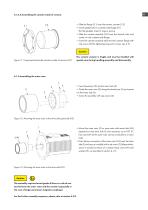
4.1.2.4 Assembling the canister made of ceramic • Slide the flange (2.1) over the ceramic canister (2.2) • Center gasket (IX) on customer-side flange (A1) (for flat gaskets). Insert O-rings in groove • Slide the canister assembly (A2) over the internal rotor and center it in the customer-side flange • Screw the canister assembly (A2) into the customer flange with cap screws (X) (for tightening torques for screws, see 4.5) Figure 11: Components/assembly canisters made of ceramic (A2) The ceramic canister is fragile and must be handled with special care during handling,assembly and disassembly....
Open the catalog to page 11All DST Dauermagnet-SystemTechnik GmbH catalogs and technical brochures
 DST product overview
32 Pages

- Shaft shaft coupling
- Torque coupling
- Transmission coupling
- Motor shaft coupling
- High-torque coupling
- Maintenance-free coupling
- Industrial coupling
- Pump coupling
- Custom-made coupling
- Shaft-hub coupling
- High-performance coupling
- ATEX coupling
- Stainless steel coupling
- Blower coupling
- Food industry coupling
- Mixer coupling
- Radial plain bearing
- Lube-free plain bearing
- Coupling for chemical applications