

- Company
- Products
- Catalogs
- News & Trends
- Exhibitions
Wiring Diagram for Use with the VF-90 Piezo Amplifier

1 / 1 PageView full catalog
Wiring Diagram for Use with the VF-90 Piezo Amplifier
Product catalog summary
Proposed Wiring Diagram for VF-90 Linear Amplifier
This document provides a wiring schematic intended for use with the VF-90 Linear Amplifier, specifically designed to drive piezoelectric loads.
Key Components and Connections
- Piezoelectric Load: The load device should be rated for voltage operation within either –30V to +150V or –30V to +200V.
- Power Supply: An AC/DC wall transformer, which is included with the VF-90 amplifier, supplies the necessary power.
- Input Signal: An analog input signal, such as from a function generator or D/A card, is used to drive the amplifier.
- Output: The amplifier provides power and ground connections to the piezoelectric (capacitive) load, for example, the FPA-500E FlexFrame PiezoActuator™.
- Voltage Supply: A +5.5V supply line is indicated as part of the wiring setup.
Critical Specifications and Recommendations
- The piezoelectric load must be compatible with the specified voltage limits to ensure safe and effective operation.
- Proper wiring according to the diagram is essential to maintain device integrity and performance.
- The use of the supplied AC/DC wall transformer is recommended to guarantee correct power delivery.
This wiring configuration ensures that the VF-90 amplifier can effectively drive piezoelectric actuators within the specified voltage ranges, maintaining device safety and performance.
See more
Catalog excerpts
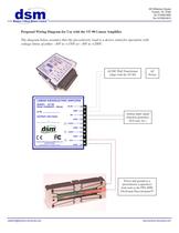
AC/DC Wall Transformer(ships with the VF-90) ACPower Analog input signal(function generator,D/A card, etc.) Power and ground to apiezoelectric (capacitive)load such as the FPA-500EFlexFrame PiezoActuator >
Open the catalog to page 1All DSM catalogs and technical brochures
 MD-90 Motor Driver
1 Page
 SA-500
1 Page
 VF-500 Voltage Follower
1 Page
 VF-90 Voltage Follower
1 Page
 Model ZSA-1000C
1 Page
 Model XSA-0200C
1 Page
 DSM Model I-20
1 Page
 SUM-40
1 Page
 XRS1-800/1600
3 Pages
 PKA-ZPR-200
1 Page
 PKA-XYZ-400
1 Page
 TTA-1200
1 Page


Archived catalogs


Related Searches
- Positioning table
- Translation stage
- Motorized positioning table
- Precision positioning table
- Single-axis positioning stage
- Manually-operated positioning stage
- 2-axis positioning table
- Rotary positioning table
- Piezoelectric stage
- 3-axis positioning table
- Actuator controller
- Linear piezoelectric actuator
- Long-travel positioning stage
- Linear actuator controller
- Amplified piezoelectric actuator
- Nanopositioning stage
- Linear nanopositioning stage
- Piezoelectric motor
- Linear piezoelectric motor
*Prices are pre-tax. They exclude delivery charges and customs duties and do not include additional charges for installation or activation options. Prices are indicative only and may vary by country, with changes to the cost of raw materials and exchange rates.
About DirectIndustry
DirectIndustry is a marketplace that offers B2B players a complete experience, from product sourcing to purchase. DirectIndustry is an entity of VirtualExpo Group.
Are you a buyer?
Are you a supplier?