- Catalogs
- DRAGO Automation GmbH
- Modbus Manual
Modbus Manual
1 /115Pages

Modbus Manual
1 /115Pages
Catalog excerpts
| AUTOMATION engineered for your success Modbus Manual DMB Series
Open the catalog to page 1
Before Startup When operating the signal converter, certain parts of the module can carry dangerous voltage! Ignoring the warnings can lead to serious injury and/or cause damage! The signal converter should only be installed and put into operation by qualified staff. The staff must have studied the warnings in these operating instructions thoroughly. The signal converter may not be put into operation if the housing is open. In applications with high operating voltages sufficient distance and isolation as well as shock protection must be ensured. Safe and trouble-free operation of this device...
Open the catalog to page 2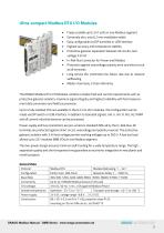
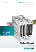
• Freely scalable up to 247 units in one Modbus segment • Extremely slim, only 6.2 mm installation width • Easy configurable via DIP switches or USB interface • Highest accuracy and temperature stability • Protective galvanic separation between all circuits, test voltage 3 kV AC • In-Rail-Bus Connector for Power and Modbus • Protection against overvoltage, polarity error and short circuit at all terminals • Long service life, extremely low failure rate due to reduced selfheating • Made in Germany, 5 Years Warranty The DRAGO Modbus RTU I/O Modules combine complex field and control requirements...
Open the catalog to page 3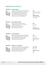
DRAGO Modbus I/O Modules DMB 96500 Universal AI Module • High performance measuring input for all industrial sensors • Uni-/Bipolar and TRMS capture of current and voltage • Easy configurable by DIP switch or USB interface • 15 User Settings, directly selectable via DIP switches • Highest accuracy, measuring resolution up to 24 bit • Fast measured value processing, high data rate Additional functions 16 V Transmitter Supply, TRMS, NAMUR Standard Signal AI Module • Precise capture of industrial standard signals • Excellent EMC performance and noise suppression • Easy configuration, fast commissioning...
Open the catalog to page 4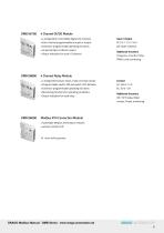
4 Channel DI/DO Module • 4 independent controllable digital I/O channels • Each channel programmable as input or output • Extensive programmable operating functions • Universal Open-Collector output • Status indication for each I/O channel Input / Output DI: 5 V / 12 V / 24 V DO: Open-Collector Frequency, Counter, Pulse, PWM, Limit monitoring 4 Channel Relay Module • 4 independent power relays, make or break contact • Programmable switch-ON and switch-OFF behavior • Extensive programmable operating functions • Monitoring functions for operating conditions • Status indication for each relay ON...
Open the catalog to page 5
DRAGO | AUTOMATION DRAGO Automation GmbH, Waldstr. 86-90, 13403 Berlin, GERMANY
Open the catalog to page 6
With the DMB series Drago Automation offers different analog and digital input options. The Modbus interface with RTU protocol on the RS485 physical layer enables robust communication in rough industrial environment. Because of their 1/8 unit load transceivers it is possible to connect 247 Drago DMB series devices as Modbus slaves with one master without the need for repeater. This manual is mainly intended to deliver devices specific information about the DMB series. Although it covers some basics about the Modbus protocol and the RS485 standard we recommend reading the referring Modbus Protocol...
Open the catalog to page 7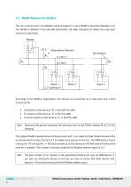
2.2 RS485 Network for Modbus The very common form of a Modbus network based on 2-wire RS485 is described detailed in [2]. The RS485 is defined in the EIA-485 (meanwhile TIA-485) standard [3]. Below the only basic structure is described: According to the Modbus Organization the devices are connected via 2 data lines and a third functional line: • Common (which is referred to as “C” in EIA/TIA-485) Because of the greater awareness this document will use the RS485 notation (A, B, C) in the following. The original RS485 standard allows 32 devices each with 1 so-called unit load. Modern devices offer...
Open the catalog to page 8
The Resistors RT are used to minimize the reflections compared to an open ended line. The optimum value of the resistor depends on the wave impedance of the cable used. However a value of 120 Ω is a common choice. The Polarization Network is needed to ensure proper potentials when none of the devices are sending and thus the lines A and B are floating. The value of RP depends on several things like bus load or termination resistors. The Modbus Organization suggests values from 450 Ω to 650 Ω for RP. The use of a polarization Network is strongly suggested to obtain a robust stable network. The...
Open the catalog to page 9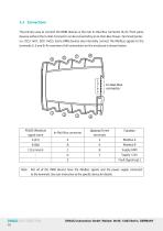
The primary way to connect the DMB devices is the rear In-Rail-Bus connector (A-E). Third-party devices without the In-Rail-Connector can be connected by an In-Rail-Bus Power-Terminals (order-no.: DZU 1401; DZU 1402). Some DMB devices also internally connect the Modbus signals to the terminals 5, 6 and 8. An overview of all connections on the enclosure is shown below: Note: Not all of the DMB devices have the Modbus signals and the power supply connected to the terminals. See user instruction of the specific device for details. DRAGO | AUTOMATION DRAGO Automation GmbH, Waldstr. 86-90, 13403 Berlin,...
Open the catalog to page 10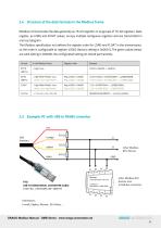
Modbus communicates the data generally as 16-bit registers or as groups of 16-bit registers. Data register, as LONG and FLOAT values, occupy multiple contiguous registers and are transmitted in one bus telegram. The Modbus specification not defines the register order for LONG and FLOAT in the transmission, so the order is configurable at register 45002 (factory setting is 0x0001). The green values below are valid setting is 0x0000, the configurated setting ist stored permanently. 2.5 Example: PC with USB to RS485 converter USB other Modbus In-Rail-Bus Power Terminal devices over In-Rail-Bus connector...
Open the catalog to page 11
DRAGO | AUTOMATION DRAGO Automation GmbH, Waldstr. 86-90, 13403 Berlin, GERMANY
Open the catalog to page 12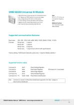
DMB 96500 Universal AI Module • High performance measuring input for all industrial sensors • Uni-/Bipolar and TRMS capture of current and voltage • Easy configurable by DIP switch or USB interface • 15 User Settings, directly selectable via DIP switches • Highest accuracy, measuring resolution up to 24 bit Additional functions • Fast measured value processing, high data rate 16 V Transmitter Supply, TRMS, NAMUR Supported communication features: Baud rates: Parity even, Parity none, Parity none, 1 stop bit (not conform with specification!) Factory setting: 19200 baud, 8 data bits, parity even,...
Open the catalog to page 13All DRAGO Automation GmbH catalogs and technical brochures
 DH 11000
2 Pages
 DH 1000
2 Pages
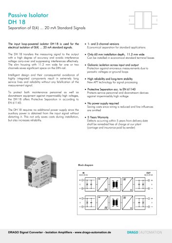 DH 18
DH 182 Pages
 Isolation Amplifier DN 28
2 Pages
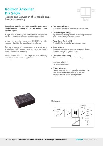 Isolation Amplifier DN 240M
2 Pages
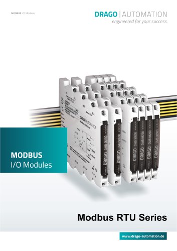 Modbus RTU Series
14 Pages
 Alarm Units
18 Pages
 High Functionality Series
22 Pages
 Tiny Snap Series
16 Pages
 6mm Series
32 Pages
 Complete Catalog
116 Pages
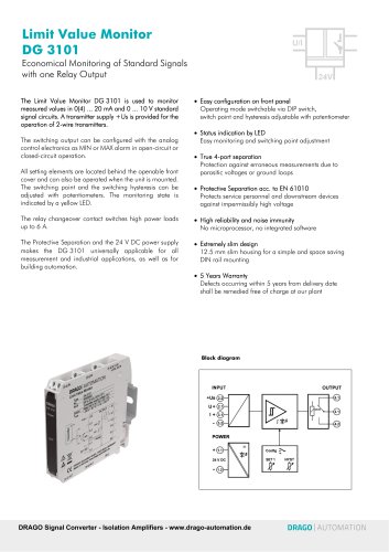 DG 3101
2 Pages
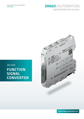 DN 2050
2 Pages
- Analog I/O
- Protection relay
- Signal amplifying integrated circuit
- Analog IO module
- Serial I/O
- Limit switch
- Temperature transmitter
- DIN rail mounted I O module
- RTD temperature transmitter
- DIN rail protection relay
- Voltage protection relay
- Measuring amplifier
- Electric motor protection relay
- Modbus RTU IO module
- Analog input module
- Configurable IO module
- Voltage I O module
- Overload relay