- Catalogs
- Dorot Control Valves
- uPVC valves
uPVC valves
1 /6Pages

uPVC valves
1 /6Pages
Catalog excerpts
uPVC Valves DESIGN SPECIFICATIONS
Open the catalog to page 1
CONCRETE SUPPORT IN LINE VALVE SUPPORT If the trench wall is not made of original soil, the T-Junction must be supported by concrete. The cement support (represented in the diagrams below) is recommended in case the bottom soil in the trench is soft or unstable. The concrete surface required to support a T-Junction with a 3" valve is 1,000 cm2. The concrete surface required to support a T-Junction with a 4" valve is 1,500 cm2. Concrete Support
Open the catalog to page 2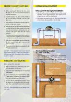
CEMENTING INSTRUCTIONS INSTALLING VALVE SUPPORT 1. Before cementing the pipe into the valve, insert the pipe into the valve and mark the point of complete penetration. Valve support for above ground installation. 2. Clean the inside of the valve and the outside of the pipe with Methyl Chloride, or at least, sand them down. The valve body is sensitive to mechanical forces, so above ground installation must be supported properly. Such support prevents collapse that may result from unstable soil. The supports must stand on solid soil. Place them on both sides of the valve, as close as possible to...
Open the catalog to page 3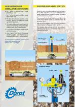
UNDERGROUND VALVE INSTALLATION INSTRUCTIONS • For 3" valves, the user should dig a trench • • • • • 500-550 mm wide. For 4" valves, the user should dig a trench 600-650 mm wide. The depth of the trenches should be at least 800 mm deep to avoid damage from agricultural machinery. The bottom of the trench should consist of original soil and be free of stones and other elements larger than 20 mm diameter. To cover the valve, the user should use soft soil free of stones. First, a layer of 100-200 mm of clean soil should be applied. After this first layer, trench soil is sufficient for further covering....
Open the catalog to page 4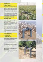
TIGHTENING BONNET BOLTS (ONLY AFTER CHANGING DIAPHRAGM) Tighten the bolts in a cross section manner using equal amounts of pressure for each bolt. Carefully tighten the bolts until the diaphragm is pressed between the valve body and bonnet. If there is leakage between the valve body and bonnet during the pressure check, it is an indication that the bolts should be tightened. UNDERGROUND VALVE PRESSURE TEST Before totally covering the trench, perform a pressure and leakage test. The test must be according to the pipe manufacturer instructions, but the pressure should not exceed 8 bar. The pressure...
Open the catalog to page 5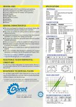
GENERAL USES ≈ Irrigation Systems (Field Valves) (Underground Installation) ≈ Anti-Frost Irrigation Systems With Underground Valves. ≈ Corrosive Water Systems For Industry And Agriculture. ≈ Sewage Systems ≈ Water Supply Systems ≈ Municipal Water Systems ≈ Landscaping ≈ Green Houses ≈ Filtration MATERIALS Body Bonnet Spring Nuts and bolts Inserted nuts Diaphragm u PVC 30 % Glass-Reinforced Polyamide SST 302 Coated Steel Brass Natural Rubber CLASSIFICATION Model Connection ≈ The valves are designed to withstand various pressures whether they are installed above ground or underground. * see below...
Open the catalog to page 6All Dorot Control Valves catalogs and technical brochures
 DAV-MP-1-KA
2 Pages
 Double-Flap Check Valve
1 Page
 Butterfly Wafer Valves
5 Pages
 DAV-MP-1-K
2 Pages
 DAV-MP-1-A
2 Pages
 DAV-WP
4 Pages
 DAV MH Series
8 Pages
 DAV MS Series
8 Pages
 Riser Valves
3 Pages
 Galil Hydraulic Valves
3 Pages
 Super Gal
8 Pages
 60ANC
60ANC2 Pages
 Plastic Valves Catalogue
8 Pages
 Series 80 Catalogue
4 Pages
 500 Series
12 Pages
 300 Series
24 Pages
 GAL Catalogue
44 Pages
 Series 100 Catalogue
36 Pages
 Angle Irrigation Valves
1 Page
 100 Series
6 Pages
 WFDBV-WF/ LU SERIES
6 Pages
 Water Meters Catalogue
8 Pages
 Turbine Water Meter
2 Pages
 Screen Filter (Stone Trap)
2 Pages
 Swing check valve
2 Pages
 DBV-WF/LU SERIES
6 Pages


- LIMING manual valve
- LIMING control valve
- LIMING water valve
- Pneumatic valve
- Electrically operated valve
- Regulating valve
- On/off valve
- Flap valve
- Check valve
- NC solenoid valve
- Pneumatically-operated valve
- Butterfly valve
- Water solenoid valve
- Hydraulic valve
- Valve with membrane
- NO solenoid valve
- Flow control valve
- Plastic valve
- Relief valve