- Products
- Catalogs
- News & Trends
- Exhibitions
Ultradepth FF, MF & SMF Coalescing Filter Elements

Ultradepth FF, MF & SMF Coalescing Filter Elements
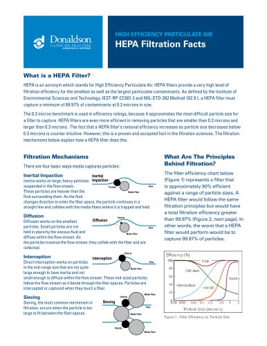
The document validates UltraDepth FF, MF, and SMF filter cartridges, emphasizing their construction, operation, and performance. These filters are engineered to eliminate oil, water, and contaminants from compressed air and gases, utilizing a patented binder-free borosilicate microfibre fleece for enhanced retention capacity and minimal pressure drop.
The filters feature aluminium end caps, stainless steel support sleeves, and a binder-free borosilicate microfibre fleece. Available in various sizes, they can be adapted to different equipment, ensuring high stability and reliability. Filtration occurs in two stages for effective contaminant removal.
Designed for diverse applications, including paint shops, the filters maintain identical filtration characteristics in both flow directions. The document outlines test arrangements and procedures for measuring differential pressure and particle separation efficiency.
Tests using a screw compressor and filter housing measured differential pressure at various flow rates, indicating pressure drop across different filter types (FF, MF, SMF) under specified conditions.
The document details the test setup for measuring particle separation efficiency using a condensation nucleus counter and differential mobility analyser, demonstrating high efficiency for all filter types.
Conducted by the Technical University of Dresden, the analysis includes differential pressure and oil aerosol retention characteristics. The test setup involved a twin-piston compressor and heat exchanger, with measurements for oil concentration and differential pressure.
Results for each filter type (FF, MF, SMF) show differential pressure as a function of oil exposure time and volume flow. The total oil removal rate and residual oil content are calculated, indicating high efficiency and low residual oil levels.
Performance data for MF 10/30 and SMF 10/30 filtration elements used for oil removal are provided. The MF 10/30 element achieves a 98.9% oil removal rate at a nominal volume flow of 720 Nm3/h and an operating pressure of 8 bar absolute, with a residual oil content of 0.03 mg/Nm3. The SMF 10/30 element shows a higher oil removal rate of 99.7% under the same conditions, with a residual oil content of 0.009 mg/Nm3.
For the SMF 10/30 element, differential pressure increases with oil exposure time, stabilizing after approximately 8 hours, indicating complete saturation. The differential pressure across fully wetted elements at nominal volume flow is 405 mbar.
Contact details for Ultrafilter company branches in Germany, Spain, and the USA are provided, including phone numbers, fax numbers, and email addresses for customer inquiries.
Catalog excerpts

FILTER CARTRIDGE VALIDATION FOR ULTRADEPTH FF, MF, SMF
Open the catalog to page 1
2 TABLE OF CONTENTS Introduction . . . . . . . . . . . . . . . . . . . . . . . . . . . . . . . . . . 3 Materials and construction . . . . . . . . . . . . . . . . . . . . . . . 4 Operation . . . . . . . . . . . . . . . . . . . . . . . . . . . . . . . . . . . . 5 Differential pressure of dry and clean filter elements . . . . . . . . . . . . . . . . . . . . . . . . . . . . . . . . 6 Degree of fractional separation of particles . . . . . . . . . .7 Differential pressure as a function of increasing oil exposure time . . . . . . . . . . . . . . . . . . 9 – 21 Differential pressure of the fully wetted...
Open the catalog to page 2
The ultrafilter oil removal filter elements of types FF , MF and SMF consist of a sandwich construction of ultrairD binder-free borosilicate microfibre fleece which is covered by a worldwide patent. These high-efficiency filters are used to remove the oil, water and contaminants which are present in compressed air, pressurised gases, air and gases under atmospheric conditions and under vacuum. The filter elements are of a robust construction and designed to operate reliably under tough operating conditions. The microfibre fleece is a depth filter material giving a void volume of 94%. Based on...
Open the catalog to page 3
4 MATERIALS AND CONSTRUCTION End caps: Aluminium, material AlCuMgPb (standard; other materials upon request) Element connection: Up to an element size at 10/30: threaded connection From size 15/30 and above: tie rod Inner support sleeve: Stainless steel, material 1.4301 Outer support sleeve: Stainless steel, material 1.4301 The support sleeves are made of flat-rolled expanded metal, thus providing a very high effective filtering surface area. Inner support fleece: Cerex Outer support fleece: Cerex Filter material: Binder-free borosilicate microfibre fleece End cap bonding: Epoxy O-ring material:...
Open the catalog to page 4
To extract the small droplets of liquids contained in compressed gases, the flow through the filter element is from the inside to the outside. The enhanced design provides filtration in two stages. Coarse contaminants are held back by the pre-filtering medium. Oil and condensate droplets are retained by the depth filter material. The droplets coalesce and are carried to the outer foam sock. The retained condensate trickles down the foam sock and accumulates at the bottom of the housing. These high-efficiency filter elements are also available in OPERATION 5 a special version for use in paint...
Open the catalog to page 5
6 DIFFERENTIAL PRESSURE OF DRY AND CLEAN FILTER ELEMENTS Test arrangement The air is compressed by a screw compressor, purified and dried by an oilfreepacD. For measurement purposes, a filter housing of type AG 0072 with a 10/30 filter element has been used. A flow regulator, placed upstream of the filter being tested, is used to set the various flow levels that are then measured downstream by a variable gas flowmeter. The differential pressure across the filter and housing is measured and recorded at the different flow rates. Upon completion of the test cycle, the initial volume flow is set...
Open the catalog to page 6
7 DEGREE OF FRACTIONAL SEPARATION OF PARTICLES The degree of fractional separation, i.e. the degree of separation of particles having almost the same size (monodisperse), as a function of the particle size is to be determined. Test arrangement and measurement procedure The test is carried out for 04/20 filter elements. The particle material selected was di-2 ethylhexyl sebacic acid (DES). The aerosol is produced by Sinclair - La Mer generator, mixed with particle-free air and then passed through either the test nit or a bypass line at a volume flow of 12 m3/h at 1 bar gauge. This method allows...
Open the catalog to page 7
9 Analysis by the Technical University of Dresden of the high-efficiency oil removal filter elements made by ultrafilter gmbH All analysis of the performance of the differential pressure and oil aerosol retention characteristics of high-efficiency oil removal filter elements of types FF, MF and SMF at the Technical University of Dresden (Germany) has been agreed with ultrafilter gmbh. The following sections describe the test conditions and measurement procedures. The results obtained are listed for each type of element. 1. Test arrangement The basic arrangement used for the test is shown below....
Open the catalog to page 9
10 A twin-piston compressor (1) is used to generate the compressed air under the following conditions: ˜ Operating pressure 7 bar ˜ Volume flow, adjustable within the range of 200 to 1,000 Nm3/h (the standard conditions are defined at an absolute pressure of 1 bar and a temperature of 20 °C) A heat exchanger (2) mounted downstream cools the compressed air to a temperature of between 20 and 30 °C. A filter housing of type AG 0072 and 10/30 filter elements were used for the measurements. Samples are taken at the inlet and the outlet of the filter (3) under isokinetic conditions for the oil aerosol...
Open the catalog to page 10
11 The mass flow through the filter is measured by an orifice flowmeter (measurement point 03) in compliance with standard DIN 1952. 2. Measurement procedure The spectrum of the oil droplets, measured directly at the inlet of the filter by the cascade impactor and absolute filter measuring device, indicates a high oil content within the droplet size range of 0.7 to 1.2 ìm. The oil concentration measured at the inlet of the filter is approximately 4 mg/Nm3. From the oil concentration at the inlet and the oil concentration at the outlet, measured by the absolute filter measuring device, the total...
Open the catalog to page 11
12 Three elements with different lot numbers for each type of filter element were independently examined under the same operating conditions. Type descriptions and lot numbers are listed below Oil removal element Lot number FF 10/30 93 08 151 93 09 364 93 12 106 MF 10/30 93 10 212 93 12 327 94 01 174 SMF 10/30 93 06 215 93 09 033 93 11 158 3. Measurement results The results of the measurements have been compiled for each type of element and incorporate the individual points of the test programme described in section 2. The results shown are mean values taken from the 3 test runs for each type...
Open the catalog to page 12All DONALDSON catalogs and technical brochures
 UFK-L Aftercoolers
2 Pages
 UFK-W Aftercoolers
3 Pages
 P-EGS
P-EGS3 Pages
 CULINARY & PROCESS STEAM
8 Pages
 Air Intake Systems
8 Pages
 Clean DEF Solutions
4 Pages
 Clean Fuel & Lubricant
32 Pages
 Exhaust System Solutions
2 Pages
 Pressure Control Systems
2 Pages
 Innovative Fuel Systems
2 Pages
 HEPA Filtration Facts
2 Pages
 AEROSPACE & DEFENSE
4 Pages
 pOWERCO RE® air cleaners
8 Pages
 Donaldson Strata™ Tubes
4 Pages
 PG-EG 0006 – 0192
6 Pages
 (P)-GS N
6 Pages
 Minerals Brochure
4 Pages
 Metals Brochure
4 Pages
 Industrial Filtration
10 Pages
 Pharma Industry - Tetratex
2 Pages
 Microfiltration
2 Pages
 Power Generation
8 Pages
 Vacuum Cleaner and Sweepers
4 Pages
 Hydraulic Filtration
320 Pages
 LDV FILTER KITS
4 Pages
 Engine Liquid Filtration
154 Pages
 Cabin Air Filtration
2 Pages
 ToriT®powercore®dusT collecTors
16 Pages
 PLEATED BAGS
3 Pages
 DALAMATIC ® DUST COLLECTORS
12 Pages
 HPK05
HPK056 Pages
 Engine Intake Systems
171 Pages
 Ultrabev P-PF-BEV
4 Pages
 Capsule Filters
8 Pages
 Oilfreepac® 2000 Standard
3 Pages
 Clean Fuel Cart X011407
1 Page
 Clean Fuel Cart X011408
1 Page
 Leakage Detector DLD
2 Pages
 SG Standard Filter Housing
7 Pages
 Clean Fuel Cart X011431
1 Page
 Venting Product Overview
2 Pages
 Vacuum Cleaners and Sweepers
4 Pages
 Chemicals Brochure
4 Pages
 DPF Thermal Regenerator IOM
16 Pages
 Adsorbent Breather Assembly
2 Pages
 Adsorbent Pouch Filter
2 Pages
 Adsorbent Breather Filter
2 Pages
 Bulk hP
4 Pages
 ULTRAPOREX SB
2 Pages
 LITHOGUARD®
2 Pages
 BSMmax
2 Pages
 Valves & Solenoids
2 Pages
 DT filter
22 Pages
 Off-Line Filtration
14 Pages
 Sight Glasses
1 Page
 Strainers
4 Pages
 Valves
6 Pages
 Breathers
14 Pages
 TT15/30/60
2 Pages
 SP100/120
4 Pages
 Low Pressure Filters
64 Pages
 WL16
WL164 Pages
 Medium Pressure Filters
38 Pages
 W613
W6134 Pages
 FPK02
FPK026 Pages
 HPK02
HPK024 Pages
 High Pressure Filters
86 Pages
 panel filter
1 Page
 GDX
GDX4 Pages
 DISK DRIVE SEALS
2 Pages
 ADSORBENT LABEL FILTER (ALF)
2 Pages
 Hydraulic Filtration
374 Pages
 Engine Liquid Filtration
132 Pages
 Oil/Water Separators
6 Pages
 SYNTEQ XP M/S
2 Pages
 Synteq XP
4 Pages
 Ultrac? AK
2 Pages
 Ultrapoly? PE
2 Pages
 ULTRAC A
2 Pages
 Dryer Package Filters
2 Pages
 SG Compressed Air Filters
2 Pages
 AG Compressed Air Filters
2 Pages
 Rotary Valves
10 Pages
 Unicell Dust Collectors
6 Pages


Archived catalogs
 Downflo Dust Collectors
6 Pages
 Unimaster® Dust Collector
4 Pages
 Sensor Vents
2 Pages
 Exhaust Product
186 Pages
 Fluid Analysis
12 Pages


- DONALDSON liquid filter
- DONALDSON cartridge filter
- Industrial use filter
- Pressure separator filter
- Stainless steel pre-filter
- DONALDSON industrial filter cartridge
- Liquids separator
- Fine filter cartridge
- Filtration unit
- Dust collector
- Dust separator filter
- Industrial fume extractor
- Water filter cartridge
- Compressed air dryer
- DONALDSON cartridge filter housing
- Panel filter
- Cascade separator
- Plastic filter cartridge