Time control technique
1 /194Pages

Time control technique
1 /194Pages
Catalog excerpts

Time control technique Technique de sécurité
Open the catalog to page 1
Safety switching devices Standstill / speed monitoring Multifunctional safety devices Wireless Safety System Safety switches Guard locks Key transfer Residual current monitors Insulation monitors Insulation fault location system Measuring and monitoring relays Fault annunciators and fault annunciator systems SMS-Telecontrol module Solid-state relays /- contactors Reversing contactors Softstarters Motor brake relays Speed and phase controllers Multifunctional motor control units Latching / interface / switching relays Interface modules Power supply units I / O modules CANopen PLC CANopen I / O...
Open the catalog to page 3
Machinery and plant Power generation/distribution Oil and gas industry Automation Transport and material handling systems Rail technology Aviation/marine industry Paper and printing industry Food industry Rubber/plastics industry Heating and refrigeration Automotive Mining/metal working Chemical/pharmaceutical applications Medical technology Water/waste water treatment Cable cars/ski lifts ... and wherever safety has high priority. We can cover your industrial applications as well!
Open the catalog to page 4
The DOLD philosophy, “Our experience. Your safety” constitutes our program: Offering solutions based on over 80 years of experience with a workforce of more than 400 employees, we manufacture high quality products using state-of-the-art production plant at our Furtwangen facility in Germany. The comprehensive product range includes relay modules, safety relays with positively-driven contacts and electronic housings with virtually unparalleled production detail. The combination of know-how, innovation and experience makes us one of the leading worldwide manufacturers. Apart from standard solutions,...
Open the catalog to page 5
Table of contents Function
Open the catalog to page 7
Alphabetical index Type
Open the catalog to page 8
Alphabetical index Type
Open the catalog to page 9
Functional index Function
Open the catalog to page 10
NC= normally closed contact, NO = normally open contact, C/O = changeover contact, FM = contact fleeting on make
Open the catalog to page 12
NC= normally closed contact, NO = normally open contact, C/O = changeover contact, FM = contact fleeting on make, Ty = thyristor, T = transistor output
Open the catalog to page 14
NC= normally closed contact, NO = normally open contact, C/O = changeover contact
Open the catalog to page 15
Applications • Delay on operate: Lead timing circuits (e.g. preheating); delay times in control systems: delayed starting of plant components, e.g. starting of slipring motors (switching starting resistors), burner controls, escalators, elevators • Release delay: After-run timing, e.g. fans, lighting controls, staircase lighting, minute lighting, delayed switching to emergency generating set/lighting Without auxiliary voltage: used for release times < 5 minutes With auxiliary voltage: used for release times > 5 minutes and for very short operating times • Flasher timers: trigger fault indicators...
Open the catalog to page 16
• According to IEC/EN 61 812-1 • 8 functions settable via rotational switch: - Delay on energisation (AV) - Fleeting on make (EW) - Delay pulse (IE) - Flasher, start with pulse (BI) - Delay on de-energisation (RV) - Pulse forming function (IF) - Fleeting on break (AW) - Delay on energisation and de-energisation (AV / RV) • 8 time ranges from 0.02 s ... 300 h selectable via rotational switches • Voltage range AC/DC 12 ... 240 V • With time interruption / time adding input • Adjustment aid for quick setting of long time values • Suitable for 2-wire proximity sensor control • 1 changeover contact •...
Open the catalog to page 17
*) A and B indicate the position of function slide switch S1 IK 7817N/200, SK 7817N/200 ® ... ® = position of function switch Delay on energisation Fleeting on make Delayed pulse Flasher, start with pulse IF = Pulse forming function AV/RV = Delay on energisation and IK 7817N/500, SK 7817N/500 © ... ® = position of function switch Delay on energisation Fleeting on make Delay pulse S1 in position A: t1: adjustable, t2 = 0.5 s fxed S1 in position B: t1 and t2 adjustable Cyclic timer, start with pulse S1 in position A TP = Cyclic timer, start with break S1 in position B IF = Pulse...
Open the catalog to page 18
Setting If the function switch is altered during operation, the new setting is valid immediately (like a restart of the relay). A new adjustment of the time or time range is also immediately valid. Please note, that a change of function, time range or time setting during elapse of time can lead to unintended switching of the output contacts. Adjustment assistance The flashing period of the yellow LED is 1 s ± 4 % and can be used to adjust the time. Especially on the lower end of scale and for long times it is suitable as the multiplication factors between the different time ranges are exact without...
Open the catalog to page 19
Technical Data Technical Data Time circuit General Data Time ranges: Time setting t1, t2: Recovery time: at DC 24 V: at DC 240 V: at AC 230 V: Repeat accuracy: Voltage and temperature influence: Input 8 time ranges in one unit, settable via rotational switch 0.02 ... 1 s 0.3 ... 30 min continuous, 1:100 on relative scale (t2 only at IK/SK 7817N/500) approx. 15 ms approx. 50 ms approx. 80 ms ± 0.5 % of selected end of scale value + 20 ms < 1 % with the complete operating range Operating mode: Temperature range: Operation: Nominal voltage UN: Voltage range: Release voltage...
Open the catalog to page 20
Standard Type IK 7817N.81/200 AC/DC 12 ... 240 V Article number: 0054359 • Output: 1 changeover contact • Nominal voltage UN: AC/DC 12 ... 240 V • Time ranges: from 0.02 s ... 300 h • Output: 1 changeover contact • Nominal voltage UN: AC/DC 12 ... 240 V • Time ranges: from 0.02 s ... 300 h Variant IK/SK 7817N.81/500: With 2 additional functions selectable via slide switch S1: - Cyclic timer, start with break (TP) - Fleeting on make and break (EW/AW) second time setting t2, connection facility for remote potentiometer 10 k^ (t1) Ordering example for variant IK 7817N .81...
Open the catalog to page 21
Control with parallel connected load L(+) Connection with 2 different control voltages.
Open the catalog to page 22All DOLD catalogs and technical brochures
 SAFEMASTER
13 Pages
 SAFEMASTER
5 Pages
 SAFEMASTER PRO
9 Pages
 VARIMETER PRO
5 Pages
 VARIMETER
7 Pages
 SAFEMASTER W group mode
9 Pages
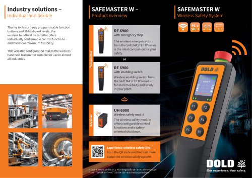
 SAFEMASTER W
9 Pages
 PCB Relays Safety Relays
148 Pages
 DOLD
DOLD3 Pages
 Speed monitor UH 6932
2 Pages
 Insulation monitor RN 5897
2 Pages
 Safety technique
626 Pages
 Installation technique
114 Pages
 Control technique
162 Pages
 Power electronics
210 Pages
 Monitoring technique
514 Pages
 News E-Mobility
3 Pages
 News 2018.01
3 Pages
 News 2017.01
5 Pages
 News 2017.02
3 Pages
 News 2016
3 Pages
 Highlights
7 Pages
 Brochure SAFEMASTER STS
20 Pages
 Flyer Option module
4 Pages
 Flyer Safety timer UG 6960
2 Pages
 Flyer Safety module UG 6970
2 Pages
 Flyer SAFEMASTER PRO
2 Pages
 Flyer enclosure KS 4460
3 Pages
 Flyer SAFEMASTER STS
2 Pages
 Catalog relay modules
909 Pages
 Enclosure overview
20 Pages
 Flyer In Rail Bus
4 Pages
 company presentation
7 Pages
 Catalog PCB relays safety relays
135 Pages


- Digital I/O
- ERLO plastic enclosure
- IO module
- ERLO mechanical lock
- Analog I/O
- Digital IO module
- Technology switch
- Wireless remote control
- Industrial remote control
- Remote control with buttons
- Protection relay
- Multipole switch
- ERLO electronic equipment enclosure
- Door lock
- Compact housing
- Steel lock
- Electromechanical switch
- Electromechanical relay
- Analog IO module