Installation technique
1 /114Pages

Installation technique
1 /114Pages
Catalog excerpts

Installation technique Technique de sécurité
Open the catalog to page 1
Safety switching devices Standstill / speed monitoring Multifunctional safety devices Wireless Safety System Safety switches Guard locks Key transfer Residual current monitors Insulation monitors Insulation fault location system Measuring and monitoring relays Fault annunciators and fault annunciator systems SMS-Telecontrol module Solid-state relays /- contactors Reversing contactors Softstarters Motor brake relays Speed and phase controllers Multifunctional motor control units Latching / interface / switching relays Interface modules Power supply units I / O modules CANopen PLC CANopen I / O...
Open the catalog to page 3
Machinery and plant Power generation/distribution Oil and gas industry Automation Transport and material handling systems Rail technology Aviation/marine industry Paper and printing industry Food industry Rubber/plastics industry Heating and refrigeration Automotive Mining/metal working Chemical/pharmaceutical applications Medical technology Water/waste water treatment Cable cars/ski lifts ... and wherever safety has high priority. We can cover your industrial applications as well!
Open the catalog to page 4
The DOLD philosophy, “Our experience. Your safety” constitutes our program: Offering solutions based on over 80 years of experience with a workforce of more than 400 employees, we manufacture high quality products using state-of-the-art production plant at our Furtwangen facility in Germany. The comprehensive product range includes relay modules, safety relays with positively-driven contacts and electronic housings with virtually unparalleled production detail. The combination of know-how, innovation and experience makes us one of the leading worldwide manufacturers. Apart from standard solutions,...
Open the catalog to page 5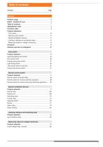
Table of contents Function
Open the catalog to page 7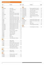
Alphabetical index Type
Open the catalog to page 8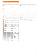
Function index Function
Open the catalog to page 9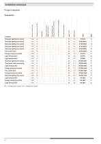
NO = normally open contact, C/O = changeover contact
Open the catalog to page 10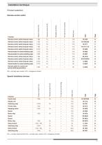
NC = normally closed contact, NO = normally open contact, C/O = changeover contact
Open the catalog to page 11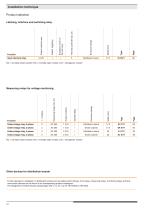
NC = normally closed contact, NO = normally open contact, C/O = changeover contact Further devices for installation in distribution boards such as safety switch devices, time relays, measuring relays, monitoring relays and fault annunciator devices can be found in the corresponding product catalogues. The designation of these devices always begin with „I“ or „R“, e.g. IK 7817N/200 or RK 5942.
Open the catalog to page 12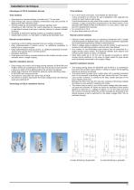
Installation technique Advantages of DOLD installation devices Time switches Time switches • for 3- and 4-wire connection, more flexible for electricians 4-wire connection is common for new installations with separate line routing for push buttons and lamps. 3-wire connections are only used if the number of conductors is limited. However, it does not meet the requirements of the latest version of the standard DIN VDE0100-460 and therefore it is only used in older systems for replacement purposes. • for currents up to 16 A • for glow lamp loads up to 50 mA • Save space by compact design, normally...
Open the catalog to page 13
Installation technique Applications of DOLD installation devices Time switches • Staircase lighting time switches in residential, business and industrial buildings ensure a safe access to staircases and save energy. • Lighting of long corridors with dimming, e.g. in hospitals, homes for the aged and public buildings • Yard lighting with automatic cutoff • After-run control for bathroom and WC fans This switch immediately switches on the light, in a toilet, for example. The fan is started with a delay of approx. one minute. Once the light is off the fan after-runs for the time set on the time...
Open the catalog to page 14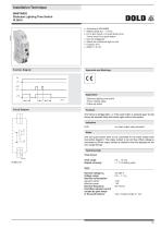
According to EN 60669 Setting range 0.5 ... 10 min. For 4-wire circuit L on push button and 3-wire circuit N on push button Can be retriggered Switch for continuous light on unit Contact: 16 A Width 17.5 mm Approvals and Markings Application - Staircase lighting time switch - Timer, release delay - Follow-up switch Circuit Diagram Function The timing is retriggerable, i.e. if the push button is pressed again during timing the adjusted delay time starts again without interruption. Indication LED: on when output relay activated Notes Unit and push button have to be connected to the same phase...
Open the catalog to page 15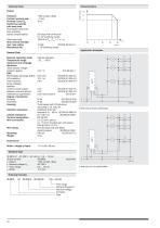
Technical Data Contacts: Contact opening gap: Thermal current Ith: Switching capacity with lamp load Fluorescent lamp load Duo switching: (series compensated) contact current Output 1 NO contact, delay < 3 mm 16 A 20 lamps with 58 W each 5 x 10⁴ switching cycles 1200 W at Tein / Taus = 1 s / 1s Glow lamp load: Short circuit strength max. fuse rating: Mechanical life: 16 AgL IEC/EN 60 947-5-1 > 106 switching cycles Application Examples General Data Vibration resistance Climate resistance: Terminal designation: Wire connection: Wire fixing: 2 kV 4 kV Limit value class B IP 40 IEC/EN 60 529 IP 20...
Open the catalog to page 16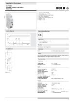
MINITIMER Staircase Lighting Time Switch IK 8810/001 DOLD According to EN 60669 Setting range 0.5 ... 10 min. For 3-wire circuit N on push button Can be not retriggered Switch for continuous light on unit Contact: 16 A Width 17.5 mm Application - Staircase lighting time switch - Timer, release delay Circuit Diagram Function The timing is not retriggerable. Indication LED: on when output relay activated Notes Unit and push button have to be connected to the same phase (see connection diagram) The output contact is not volt free. Technical Data Time Circuit Time range: 0.5 ... 10 min Repeat...
Open the catalog to page 17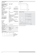
Technische Daten General Data Nominal operating mode: Temperature range: Clearance and creepage distances rated impulse voltage / pollution degree: EMC Electrostatic discharge (ESD): HF-irradiation: Fast transients: Surge voltages between wires for power supply: between wire and ground: Interference suppression: Degree of protection Housing: Terminals: Housing: Vibration resistance Climate resistance: Terminal designation: Wire connection: 2 kV 4 kV Limit value class B Wire fixing: Mounting: Weight: EN 50 005 2 x 2.5 mm2 solid or 2 x 1.5 mm2 stranded wire with sleeve DIN 46 228-1/-2/-3/-4 Flat...
Open the catalog to page 18All DOLD catalogs and technical brochures
 SAFEMASTER
13 Pages
 SAFEMASTER
5 Pages
 SAFEMASTER PRO
9 Pages
 VARIMETER PRO
5 Pages
 VARIMETER
7 Pages
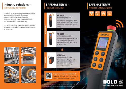
 SAFEMASTER W group mode
9 Pages
 SAFEMASTER W
9 Pages
 PCB Relays Safety Relays
148 Pages
 DOLD
DOLD3 Pages
 Speed monitor UH 6932
2 Pages
 Insulation monitor RN 5897
2 Pages
 Safety technique
626 Pages
 Time control technique
194 Pages
 Control technique
162 Pages
 Power electronics
210 Pages
 Monitoring technique
514 Pages
 News E-Mobility
3 Pages
 News 2018.01
3 Pages
 News 2017.01
5 Pages
 News 2017.02
3 Pages
 News 2016
3 Pages
 Highlights
7 Pages
 Brochure SAFEMASTER STS
20 Pages
 Flyer Option module
4 Pages
 Flyer Safety timer UG 6960
2 Pages
 Flyer Safety module UG 6970
2 Pages
 Flyer SAFEMASTER PRO
2 Pages
 Flyer enclosure KS 4460
3 Pages
 Flyer SAFEMASTER STS
2 Pages
 Catalog relay modules
909 Pages
 Enclosure overview
20 Pages
 Flyer In Rail Bus
4 Pages
 company presentation
7 Pages
 Catalog PCB relays safety relays
135 Pages


- Digital I/O
- ERLO plastic enclosure
- IO module
- ERLO mechanical lock
- Analog I/O
- Digital IO module
- Technology switch
- Wireless remote control
- Industrial remote control
- Remote control with buttons
- Protection relay
- Multipole switch
- ERLO electronic equipment enclosure
- Door lock
- Compact housing
- Steel lock
- Electromechanical switch
- Electromechanical relay
- Analog IO module