TDR9100
1 /2Pages

TDR9100
1 /2Pages
Catalog excerpts
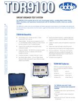
CIRCUIT BREAKER TEST SYSTEM The TDR9100 is the essential test set for your circuit breaker testing - providing Main Contact timing, Motion, Resistance and Capacitance measurements with the flexibility to double or triple your useable channels. The TDR9100 is a state-of-the-art Circuit Breaker Test System engineered to test all types of circuit breakers with efficient and accurate performance measurements. Use this inclusive, rugged and field-portable instrument for simple and complex testing of circuit breakers. T est set features up to 4 breaks per phase, 3 motion channels and 6 event channels Testing Flexibility - The test set can be ganged as a set of 2 or 3 units effectively doubling or tripling your usable channels and main contacts for up to 12 breaks per phase. H igh Accuracy Motion Recording - A patented digital rotary and linear transducer provide early diagnosis of mechanical problems. Includes Pre-insertion resistor and Capacitance measurement Supports 20kHz sampling rate and expanded analog measurement ranges Detects main contact and resistor contact timing errors Supports Doble Current Probe and other analog transducers R ugged and Reliable - The TDR9100 is a single box solution, providing the accuracy of a laboratory instrument with durability for field use. Complete Test Reports - provided in MS Excel™ format I mmune to Interference - The accuracy of test results is unaffected by the severe conditions of electrostatic and electromagnetic interference that are normally present in harsh substation environments. U ser-friendly software interface - The new T-Doble Software features an intuitive control panel for quick, efficient and simple testing of circuit breakers. Controlled by user supplied PC TDR9100 Features: TDR9100 controls circuit breaker trip and close commands and supports the following operations: • Trip (O) • O-CO • Close (C) • O-0.3s-CO • Reclose (O-0.3s-C) • First Trip (O) • Tripfree (CO) • Slow Close (C) The TDR9100 comes with T-Doble Software for improved data management capability. • ntuitive and clear: easy-to-use test plans and I test results • ata can be plotted, overlaid, analyzed and D printed • ill import all TRX and T-Doble test result data W and test plans
Open the catalog to page 1
Motion Channels Number of Channels: Connector: Voltage Isolation to Chassis: 3 - up to 9 with ganged units 15-pin “D” 1.0 kV Event Channels Dual function, Analog or Auxiliary, user programmable Number of Channels: 6 - up to 18 with ganged units Analog Measurement Channels Maximum Input Voltage: Input Impedance: Resolution: Number of Ranges: Analog Accuracy: Voltage Isolation to Chassis: ± 300 V 1 MΩ 12 Bit Ten - 0.2 to 300 V ± 1% of reading, ± 1.5% full scale offset 1.0 kV Voltage Sense/Contact Sense ± 300 V 30 V ± 10% 28 mA ± 10% 1.0 kV Auxiliary Contact Channels • .C.B. & EHV Contact Cable...
Open the catalog to page 2All Doble Engineering Company catalogs and technical brochures
 M5400
M54002 Pages
 Leakage Current Monitor
2 Pages
 F6080 Field Calibration Unit
2 Pages
 Current Probe (AC/DC)
2 Pages
 F6816
F68162 Pages
 F5814
F58144 Pages
 Delphi
2 Pages
 M7100
M71001 Page
 dobleARMS
2 Pages
 PRODUCT OVERVIEW
8 Pages


- Portable analyzer
- Automatic test kit
- Insulation testing system
- Electrical network analyzer
- Digital test equipment
- Spectrum analyzer
- Voltage amplifier
- Relay testing device
- Current amplifier
- Clamp ammeter
- Circuit breaker testing device
- Electrical resistance test kit
- Benchtop amplifier
- Detector tester
- Partial discharge monitor
- Portable partial discharge monitor