
- Catalogs
- DJB Instruments UK Ltd
- CA/04/N,

CA/04/N,

CA/04/N,
- Input Range: Up to 3.16V/pC.
- Frequency Response: 0.1/100 kHz.
- Noise Level: Dominated by input voltage noise, influenced by signal source impedance and charge amplifier transfer impedance.
- Output Normalizing: A three-decade digi-switch and x1/x10 multiplier provide output normalizing over a 1/110pC/g transducer sensitivity range with 1% resolution.
- Output Settings: O/P1 calibrated to 10mV/g and O/P2 to 1V for various range settings.
- CA/04/NL: 0.1/11pC/g
- CA/04/N: 1/110pC/g
- CA/04/NH: 10/1100pC/g
- CA/04/EH: 100/11000pC/g
- Input: Single-ended with a maximum input charge of 100nC, reducing at 6dB/octave for frequencies above 30kHz.
- Noise Level: 0.004pC rms + 0.004pC rms/1nF input capacitance.
- Outputs: O/P1 and O/P2 with selectable 10dB increments, peak output voltage of ±12V, and peak output current of ±10mA.
- Calibration: The CAL terminal connects to the amplifier input via a 1nF capacitor, converting applied voltage to input charge.
- Overload Indicator: An absolute value peak detector indicates when the signal level exceeds 8V.
Catalog excerpts

SENSING ENGINEERING INNOVATION CA/04/N, NL, NH, EH Charge amplifier: 04 system Low noise, extended low frequency response; input range, output up to 3.16V/pC, overload LED; bandwidth 0.1/100 kHz CHARGE AMPLIFIER NOISE The dominant source is input voltage noise, amplified by the non-inverting gain of the transducer interface section (Fig.I.). This latter is a function of the signal source impedance, 1/w (Ct + Cc), and charge amplifier transfer impedance 1/w Cf being unity (best case) for open circuit input. Note also that in the O/C input case, increased transfer impedance improves signal/noise by prorate enhancement of the inverting/no inverting gain ratio. It is safe to say that noise evaluation and comparison should be subject to representative input loading-open circuit data may mislead. Minimal noise design centres on the choice of early stage active devices and their configuration; ergonomic facets contributing to operational versatility may override absolute minimisation. CA/04/N Low noise charge amplifier, with a 0.1/1 Hz (-3dB) switchable minimum frequency option, provision for adding custom single pole low pass roll-off, LED overload indicator. NORMALISING A three decade digi-switch and x1/x10 multiplier provides output normalising over a 1/110pC/g transducer sensitivity range, with 1% worst case resolution. Min. (1.00), max. (10.99) digi-switch settings confine range to minimum 1% resolution, caters for 10 & 100pC/g transducer nominal sensitivity tolerance spread. OUTPUTS Setting digi-switch and multiplier directly to the transducer charge sensitivity calibrates O/P1 to 10mV/g, O/P2 to 1V for range switches setting 0.316, 1.0, 3.16, 10, 31.6, or 100g. Normalising scale factor greater than unity produces a pro-rata gain reduction, hence O/P1 & 2 scaling, and increase in peak g. Finchley Avenue, Email [email protected] Mildenhall, Suffolk IP28 7BG Web www.djbinstruments.com A UK company with UK-based manufacturing, assembly and calibration in-house.
Open the catalog to page 1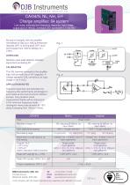
SENSING ENGINEERING INNOVATION CA/04/N, NL, NH, EH Charge amplifier: 04 system Low noise, extended low frequency response; input range, output up to 3.16V/pC, overload LED; bandwidth 0.1/100 kHz By way of example, with the amplifier normalised to 50pC/g a 10pC/g transducer rescales O/P1 to 2mV/g peak O/P1 level will increase from 1200 to 6000g (Vs = ±15V). OVERLOAD Absolute value peak detector indicates signal level exceeding 8V. CALIBRATION The CAL terminal connects to the amplifier input (virtual earth) via a 1nF capacitor. A voltage applied to CAL converts to an input charge (1mV = 1pC). APPLICATION...
Open the catalog to page 2All DJB Instruments UK Ltd catalogs and technical brochures
 VS1 Handheld Vibration Meter
2 Pages
 MIL-C-5015/MIL-DTL-5015
1 Page
 IEPE Sensor Simulator
1 Page
 New Reference Technical Guide
36 Pages
 V3/04
V3/041 Page
 VS1
VS12 Pages
 CV1
CV11 Page
 CA/100/F
1 Page
 CA/04/V
2 Pages
 VB/01
VB/011 Page
 IEPE Impact Hammer Range
1 Page
 AF IEPE Impedance Head
1 Page
 A/161
A/1611 Page
 A/122/V
2 Pages
 A/107/F
1 Page


Archived catalogs
 Technical Reference Guide
24 Pages
 Connectors
3 Pages
 Cables, cables armour
2 Pages
 Joiners
1 Page
 Accelerometer mounting studs
3 Pages


- Acceleration sensor
- Piezoelectric accelerometer
- Single-axis accelerometer
- IEPE accelerometer
- Triaxial acceleration sensor
- Compact accelerometer
- Signal conditioner
- General purpose accelerometer
- Industrial accelerometer
- Voltage output accelerometer
- Miniature accelerometer
- Analog signal conditioner
- Accelerometer for automotive applications
- High-temperature accelerometer
- Adhesive accelerometer
- Amplifier signal conditioner
- Multi-channel signal conditioner
- Seismic sensor
- Ultraminiature accelerometer
- Modular signal conditioner