- Catalogs
- Displaytech
- DT024CTFT & DT024CTFT-TS
DT024CTFT & DT024CTFT-TS
1 /13Pages
DT024CTFT & DT024CTFT-TS
1 /13Pages
Catalog excerpts
a seacomp company Website: www.displaytech.com.hk Contents in this document are subject to change without notice. No part of this document may be reproduced or transmitted in any form or by any means, electronic or mechanical, for any purpose, without the express written permission of Displaytech Ltd.
Open the catalog to page 1
Displaytech Ltd LCD MODULE DT024CTFT / DT024CTFT-TS Version: 1.0
Open the catalog to page 2
Displaytech Ltd LCD MODULE DT024CTFT / DT024CTFT-TS Version: 1.0
Open the catalog to page 3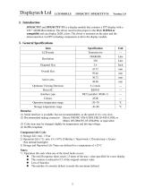
Displaytech Ltd LCD MODULE DT024CTFT / DT024CTFT-TS Version: 1.0 DT024CTFT and DT024CTFT-TS is a display module that contains a TFT display with a 320 * 240 RGB resolution. The driver used for this project is the Ilitek ILI9341 or compatible and can display 262K colors. The driver is mounted on the glass and the interconnection via FPC including components to drive the display module. (1) Serial interface is available, but not recommendable, as the speed of it is very slow. (2) Recommended mating connector: Hirose FH19SC-45S-0.5SH, FH12S-45S-0.5SH; or (3) Color tune may be changed slightly by...
Open the catalog to page 4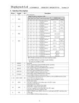
Displaytech Ltd lcd module5. Interface Description Pin no - Select the MCU interface mode IM3 MPU Parallel interface bus and serial interface selectIf use RGB Interface must select serial interface.*: Fix this pin at VDDI or VSS. Reset pin. Frame synchronizing signal for RGB interface operation. Fix to VDDI or VSS level when not in use. Line synchronizing signal for RGB interface operation. Fix to VDDI or VSS level when not in use. Dot clock signal for RGB interface operation. Fix to VDDI or VSS level when not in use. Data enable signal for RGB interface operation. Fix to VDDI or VSS level when...
Open the catalog to page 7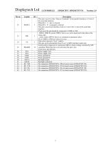
Displaytech Ltd LCD MODULE DT024CTFT / DT024CTFT-TS Version: 1.0
Open the catalog to page 8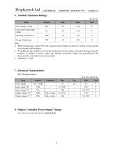
Displaytech Ltd LCD MODULE DT024CTFT / DT024CTFT-TS Version: 1.0 See Display Controller Specification: Ilitek ILI9341
Open the catalog to page 9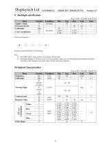
Displaytech Ltd LCD MODULE DT024CTFT / DT024CTFT-TS Version: 1.0
Open the catalog to page 10
The data are measured after LEDs are turned on for 5 minutes. LCM displays full white. The brightness is the average value of 9 measured spots. Measurement equipment PR-705 (Φ8mm) Measuring condition: - Measuring surroundings: Dark room. - Measuring temperature: Ta=25°C. - Adjust operating voltage to get optimum contrast at the center of the display. Measured value at the center point of LCD panel after more than 5 minutes while backlight turning on. The luminance uniformity is calculated by using following formula. ∆Bp = Bp (Min.) / Bp (Max.)×100 (%) Bp (Max.) = Maximum brightness in 9 measured...
Open the catalog to page 11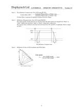
DT024CTFT / DT024CTFT-TS Version: 1.0 Note 4: The definition of contrast ratio (Test LCM using PR-705): Luminance When LCD is at “White” state Luminance When LCD is at Black state (Contrast Ratio is measured in optimum common electrode voltage) Note 5: Definition of Response time. (Test LCD using DMS501): The output signals of photo detector are measured when the input signals are changed from “black” to “white” (falling time) and from “white” to “black” (rising time), respectively. The response time is defined as the time interval between the 10% and 90% of amplitudes. Refer to figure as below....
Open the catalog to page 12
Displaytech Ltd11. Safety PrecautionHandling precautions: • This device is susceptible to Electro-Static Discharge (ESD) damage. Observe Anti-Static precautions. • Identify and, at all times, observe absolute maximum ratings for both logic and LC drivers. Note that there is some variance between models. • Prevent the application of reverse polarity to VCC and GND, however briefly. • Use a clean power source free from transients. Power up conditions are occasionally “jolting” and may exceed the maximum ratings of the modules. • The VCC power of the module should also supply the power to all devices...
Open the catalog to page 13All Displaytech catalogs and technical brochures
 DT024ETFT-IPS, DT024ETFT-IPS-SHB
17 Pages
 DT024DTFT
11 Pages
 DT018BTFT, DT018BTFT-SHB
17 Pages
 DT018ATFT
12 Pages
 DT010ATFT
13 Pages
 64240C-Series
22 Pages
 64128Q-Series
24 Pages
 64128P-Series
22 Pages
 64128N-Series
19 Pages
 64128M-Series
21 Pages
 64128LX-Series
21 Pages
 64128L-Series
21 Pages
 64128KX-Series
21 Pages
 64128K-FC-BW-RGB
25 Pages
 32128A-Series
19 Pages
 128240D-RGB-Series
21 Pages
 128240D-Series
21 Pages
 128240C-RGB-Series
21 Pages
 128240C-Series
21 Pages
- Power supply unit
- DC power supply
- AC/DC power supply
- LCD display panel
- CE power supply
- Compact power supply
- Lithium battery
- IEC battery
- Graphic display panel
- Rectangular battery
- RoHS power supply
- RGB display panel
- Adjustable thermostat
- UL power supply
- SPI display
- Monochrome display
- Dot-matrix display panel
- Digital thermostat
- Power supply with USB outlet