- Catalogs
- Displaytech
- 32128A-Series
32128A-Series
1 /19Pages
32128A-Series
1 /19Pages
Catalog excerpts
Website: www.displaytech.com.hk Product: 32128A Series Monochrome Graphic Display Module (128x32DOTS) Contents in this document are subject to change without notice. No part of this document may be reproduced or transmitted in any form or by any means, electronic or mechanical, for any purpose, without the express written permission of Displaytech Ltd.
Open the catalog to page 1
1. REVISION RECORD VERSION
Open the catalog to page 2
Displaytech Ltd LCD MODULE 32128A SERIES Version: 2.1
Open the catalog to page 3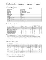
2. General Specifications Item 5. Display Controller /Power Supply Timing See Display Controller Specification: Sitronix ST7565V
Open the catalog to page 4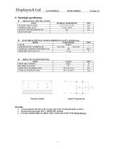
9. Backlight specification CIRCUIT DIAGRAM • MECHANICAL SPECIFICATIONS 1. Average luminous intensity is the average value of the six indicated points as shown. 2. Measurement instrument: BM-7, APERTURE: 010mm. 3. IT IS RECOMMENDED TO DRIVE THE LED BACKLIGHT WITH PWM SIGNAL.
Open the catalog to page 8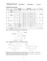
NOTE 1: DEFINITION OF VIEWING ANGLE AND DIRECTION NOTE 2: THERSHOLD VOLTAGE AND SATURATION VOLTAGE Vth: The voltage Vop which the transmission rate of segment is 90%(positive) or 10%(negative) of saturated value on conditions of the selected waveform.(non-selected waveform is opposition) Vsat: The voltage Vop which the transmission rate of segment is 10%(positive) or 10%(negative) of saturated value on conditions of the selected waveform.(non-selected waveform is opposition)
Open the catalog to page 9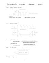
NOTE 3: CURRENT CONSUMPTION (I LCD) Conditions: 1.Driving waveform: static waveform. NOTE 4: RESPONSE TIME (Tr, Tf) NOTE 5: CONTRAST RATIO (CR) 5.1 POSITIVE TYPE: CONTRAST RATIO = BRIGHTNESS AT VOP(NON-SELECTED) BRIGHTNESS AT VOP(SELECTED) 5.2 NEGATIVE TYPE: CONTRAST RATIO = BRIGHTNESS AT VOP(SELECTED) BRIGHTNESS AT VOP(NON-SELECTED) Conditions: Voltage applied to all segments.
Open the catalog to page 10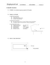
ll.Quality Guarantee • PURPOSE: It is to define the inspection standard of LCD modules • PRODUCT STANDARD • FUNCTION TEST • APPEARANCE INSPECTION • PACKING SPECIFICTION • Put under the lamp (20wx2) at a distance 100mm from the LCD Modules. • Tilt upright 45 degree by the front (back) to inspect LCD appearance. • SAMPLING METHOD • SAMPLING PLAN • MAJOR DEFECT • MINOR DEFECT • GENERAL LEVEL 0.65% (MAJOR) 2.5% (MINOR) II/NORMAL • DISPLAY AREA DEFINITION:
Open the catalog to page 11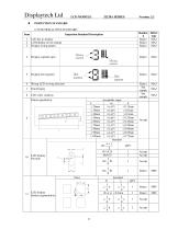
INSPECTION STANDARD 1) FUNCTIONAL TEST STANDARD Item Inspection Standard Description Standar d Defect type Display wrong pattern Display segment open Wrong LCD viewing direction Pattern parallelism LCD display Broken segment(dots)
Open the catalog to page 12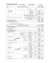
2) COSMETIC INSPECTION STANDARD
Open the catalog to page 13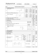
Standard description of inspection Standard PCB/COB specification PCB deformity Deformity at PCB edge, damage circuit. Damage excess 2x2mm at the PCB corner Scratch on PCB surface Scratch on PCB coat/leakage coat on PCB surface Open circuit PCB PTH open Color different from one side to another side. Repaired solder mask area Scratch circuit, damage Circuit Accept Reject Reject Reject Reject See sample Reject Reject Reject Accept Reject Reject Accept Reject Bezel specification Wrong Materials Incorrect dimension Bezel broken Rust on Bezel Hole or dirty on oil Paint surface
Open the catalog to page 14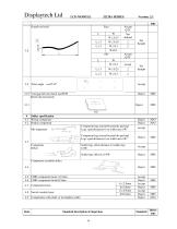
Void gap between bezel and PCB Bezel clip incorrectly Solder specification Wrong component Broken component Component legs extend beyond the pad and Legs >pad distance(w) on solder area >W2 Component legs extend beyond the pad and Legs >pad distance(w) on solder area <W2 Solder legs offset distance L<solder legs 1/4W Solder legs offset L>1/4W Component assembly defect Components hoist Switch (socket) hoist Components cold solder or incomplete solder
Open the catalog to page 15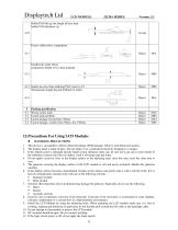
• HANDLING PRECAUTIONS 1. This device is susceptible to Electro-Static Discharge (ESD) damage. Observe Anti-Static precautions. 2. The display panel is made of glass. Do not subject it to a mechanical shock by dropping it or impact. 3. If the display panel is damaged and the liquid crystal substance leaks out, be sure not to get any in your mouth. If the substance contacts your skin or clothes, wash it off using soap and water. 4. Do not apply excessive force to the display surface or the adjoining areas since this may cause the color tone to vary. 5. The polarizer covering the display surface...
Open the catalog to page 16
13. To prevent destruction of the elements by static electricity, be careful to maintain an optimum work environment. • Be sure to ground the body when handling the LCD modules. • Tools required for assembling, such as soldering irons, must be properly grounded. • To reduce the amount of static electricity generated, do not conduct assembling and other work under dry conditions. • The LCD module is coated with a film to protect the display surface. Exercise care when peeling off this protective film since static electricity may be generated. • POWER SUPPLY PRECAUTIONS: 1. Identify and, at all...
Open the catalog to page 17
1. Please keep the temperature within specified range for use and storage. Polarization degradation, bubble generation or polarizer peel-off may occur with high temperature and high humidity. 2. Do not touch, push or rub the exposed polarizers with anything harder than an HB pencil lead (glass, tweezers, etc.). 3. N-hexane is recommended for cleaning the adhesives used to attach front/rear polarizers and reflectors made of organic substances which will be damaged by chemicals such as acetone, toluene, ethanol and isopropylalcohol. 4. When the display surface becomes dusty, wipe gently with absorbent...
Open the catalog to page 18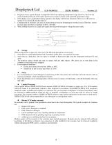
3. Response time is greatly delayed at temperature below the operating temperature range. However, this does not mean the LCD will be out of the order. It will recover when it returns to the specified temperature range. 4. If the display area is pushed hard during operation, the display will become abnormal. However, it will return to normal if it is turned off and then back on. 5. Condensation on terminals can cause an electrochemical reaction disrupting the terminal circuit. Therefore, it must be used under the relative condition of 40°C , 50% RH. 6. When turning the power on, input each signal...
Open the catalog to page 19All Displaytech catalogs and technical brochures
 DT024ETFT-IPS, DT024ETFT-IPS-SHB
17 Pages
 DT024DTFT
11 Pages
 DT024CTFT & DT024CTFT-TS
13 Pages
 DT018BTFT, DT018BTFT-SHB
17 Pages
 DT018ATFT
12 Pages
 DT010ATFT
13 Pages
 64240C-Series
22 Pages
 64128Q-Series
24 Pages
 64128P-Series
22 Pages
 64128N-Series
19 Pages
 64128M-Series
21 Pages
 64128LX-Series
21 Pages
 64128L-Series
21 Pages
 64128KX-Series
21 Pages
 64128K-FC-BW-RGB
25 Pages
 128240D-RGB-Series
21 Pages
 128240D-Series
21 Pages
 128240C-RGB-Series
21 Pages
 128240C-Series
21 Pages
- DC power supply
- AC/DC power supply
- CE power supply
- Compact power supply
- Lithium battery
- IEC battery
- Graphic display panel
- Rectangular battery
- RGB display panel
- RoHS power supply
- Adjustable thermostat
- SPI display
- UL power supply
- Monochrome display
- Dot-matrix display panel
- Digital thermostat
- Power supply with USB outlet