Group: Sensors

Catalog excerpts

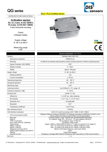
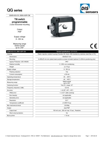
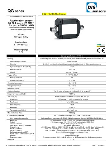
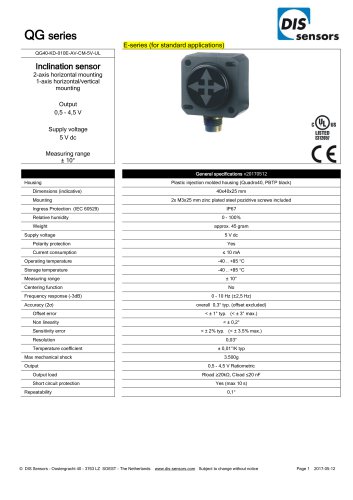
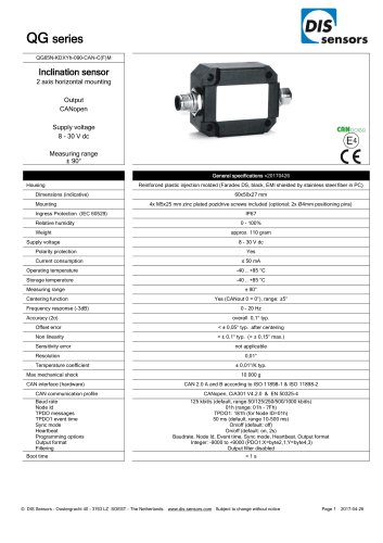
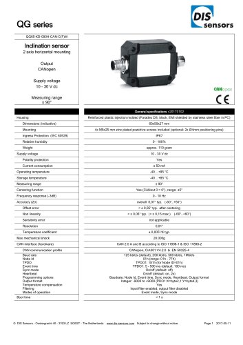
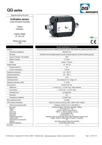
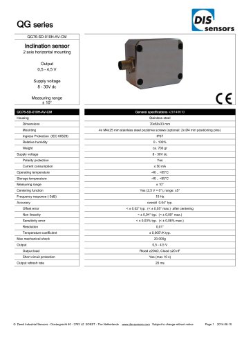
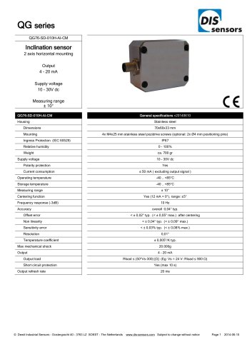
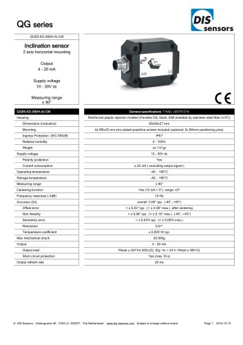
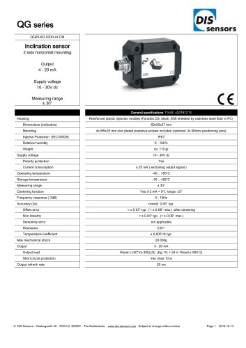
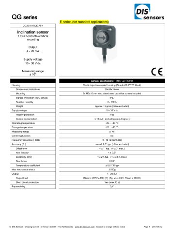
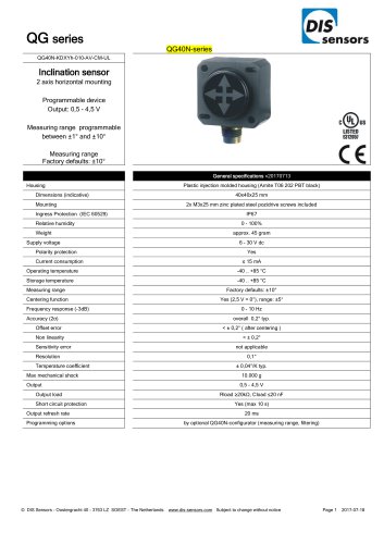
L. sensorsQG40N-series QG40N-KIXv-170-ASN-CM-UL Tilt switch 1 axis vertical mounting Programmable device Output: NPN Switch points programmable between ±1° and ±170° Measuring range Factory defaults: ±90° & ±170° Plastic injection molded housing (Arnite T06 202 PBT black) Dimensions (indicative) Mounting Ingress Protection (IEC 60529) Relative humidity Weight Supply voltage Polarity protection Current consumption Operating temperature Storage temperature Measuring range Centering function Frequency response (-3dB) Accuracy (2o) Offset error Non linearity Sensitivity error Resolution Temperature coefficient Max mechanical shock Output Output load Short circuit protection Boot time Programming options 2x M3x25 mm zinc plated steel pozidrive screws included IP67 150 mA cont., 250 mA max 10 sec., protected against back EMF Yes (max 10 s) by optional QG40N-configurator (switch points, delay times, filtering) © DIS Sensors - Oostergracht 40 - 3763 LZ SOEST - The Netherlands www.dis-sensors.com Subject to change without notice
Open the catalog to page 1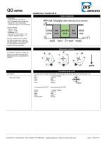
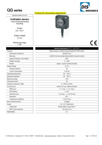
NPN-output: - Programmable switchpoints - at 0°: operation zone, conducting - critical zone: non-conducting - Unpowered sensor: non-conducting Factory defaults: - output 1: ±90° - output 2: ±170° - hysteresis : 0,5° - operation ► critical delay : 0,5 s - critical ► operation delay : 1 s Zeroing: eliminate mech. offsets Connect zeroingr input to ground (>0,5sec) within 1 min. after power up. Normally the zeroing input should be left unconnected. NPN Out (Vsupply) (with external pull-up resistor) A critical zone -out2 -outl 0 +out1 +out2 The default 0° position is when the sensor is mounted...
Open the catalog to page 2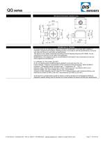
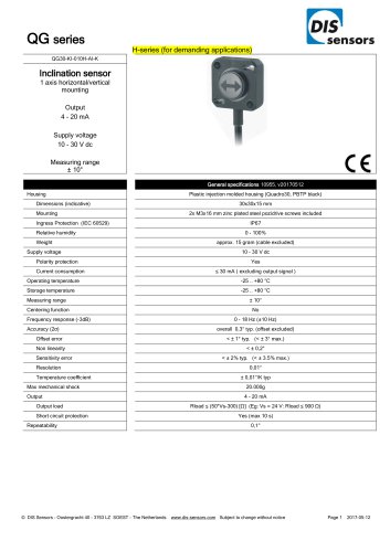
QG series Mechanical dimensions (indicative only) Intended use, UL, Remarks QG series sensors are intended to measure inclination, acceleration or tilt angle after installing in machines, equipment and systems. Flawless function in accordance with the specifications is ensured only when the device is used within its specifications. This device is not a safety component according to the EU Machine Directive (ISO13849). For full redundancy two devices can be used in the application. Modifications or non-approved use are not permitted and will result in loss of warranty and void any claims...
Open the catalog to page 3All DIS Sensors catalogs and technical brochures
-
 QG65/76 configurator
1 Pages
-
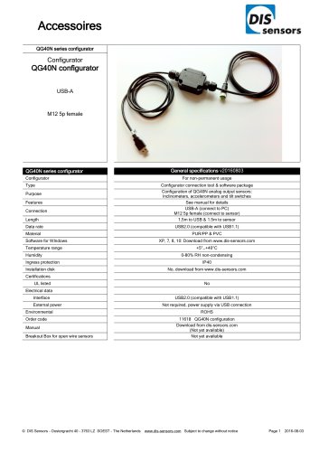 QG40N series configurator
1 Pages
-
 N35H - Ø 15 x 4 mm
1 Pages
-
 N35H - Ø 8 x 5 mm
1 Pages
-
 N42 - 20 x 12 x 10 mm
1 Pages
-
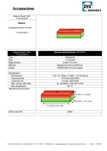 N35 - 11,2 x 5,5 x 8 mm
1 Pages
-
 Plastic disc - 30 x 8 mm
1 Pages
-
 Stainles steel - 12 x 20 mm
1 Pages
-
 5p, female
2 Pages
-
 5p, male
2 Pages
-
 5-pole, 1x male & 2x female
2 Pages
-
 Female, 8-pole, plastic
2 Pages
-
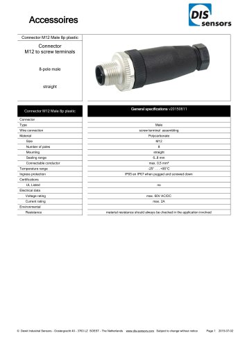 Male, 8-pole, plastic
2 Pages
-
 Female, 5-pole, plastic
2 Pages
-
 Female, 5-pole, metal
2 Pages
-
 Male, 5-pole, plastic
2 Pages
-
 Male, 5-pole, metal
2 Pages
-
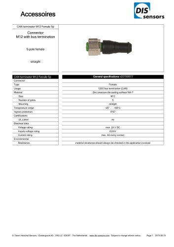
 CAN - PUR 1x M12, female, 5p
2 Pages
-
 Cable PUR 1x M12 Female 5p
2 Pages
-
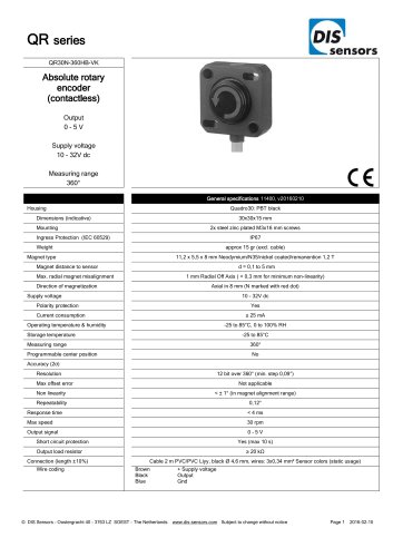
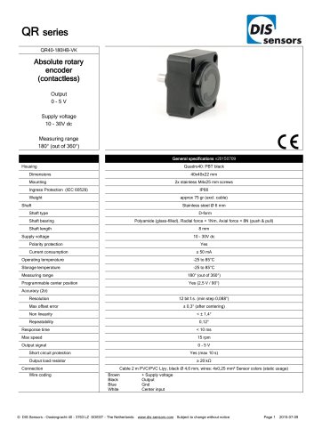 QR40-180HB-VK
2 Pages
-
 QR40-360HA-P-K
2 Pages
-
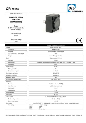 QR40-360HB-VK-5V
2 Pages
-
 QR40-360HB-VK
2 Pages
-
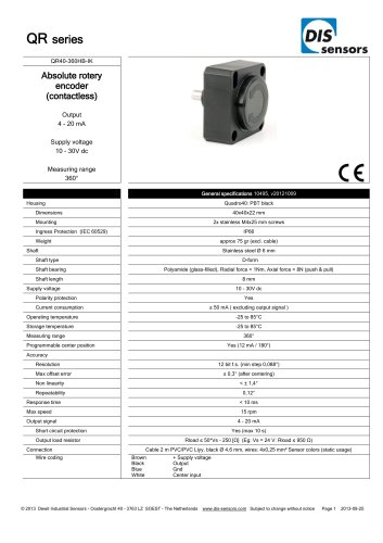 QR40-360HB-IK
2 Pages
-
 QR40-180HB-IK
2 Pages
-
 QR40-090HB-VK
2 Pages
-
 QR40-090HB-IK
2 Pages
-
 QR30-360PI-CK
2 Pages
-
 QR30-360NI-CK
2 Pages
-
 QR30-360MI-CK
2 Pages
-
 QR30-360LI-CK
2 Pages
-
 QR30-360KI-CK
2 Pages
-
 QR30N-360HB-VK
2 Pages
-
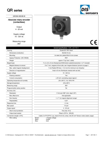 QR30N-360HB-IK
2 Pages
-
 QR30N-180HB-VK
2 Pages
-
 QR30N-180HB-IK
2 Pages
-
 QR30N-090HB-IK
2 Pages
-
 QR30N-090HB-VK
2 Pages
-
 QR40EMN-360HB-V-CM-UL
2 Pages
-
 QR40EMN-360HB-2I-CM-UL
2 Pages
-
 QR40EMN-360HB-2V-CM-UL
2 Pages
-
 QR40EMN-090HB-I-CM-UL
2 Pages
-
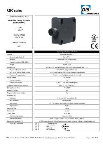 QR40EMN-360HB-I-CM-UL
2 Pages
-
 QR40EMN-090HB-V-CM-UL
2 Pages
-
 QG76-SD-001..025H-ASP-CM
2 Pages
-
 QG65-KD-010..060H-ASP-CM
2 Pages
-
 QG65-KD-010..060H-ASN-CM
2 Pages
-
 QG65-KD-001..025H-ASN-CM
2 Pages
-
 QG65-KD-001..025H-ASP-CM
2 Pages
-
 QG40N-KDXYh-080-ASP-CM-UL
3 Pages
-
 QG40N-KDXYh-080-ASN-CM-UL
3 Pages
-
 QG40N-KIXv-170-ASP-CM-UL
3 Pages
-
 QG65N-KAXYZ-8-CANS-C(F)M-2d
2 Pages
-
 QG65N-KAXYZ-8-CAN-C(F)M
2 Pages
-
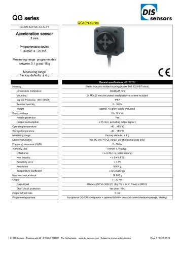
 QG40N-KAXYZ-16,0-AI-PT
3 Pages
-
 QG40N-KAXYZ-16,0-AV-PT
3 Pages
-
 QG40N-KAXYZh-4,0-AI-PT
3 Pages
-
 QG40N-KAXYZh-1,5-AV-PT
3 Pages
-
 QG40N-KAXYZh-1,5-AI-PT
3 Pages
-
 QG40N-KAXYZh-4,0-AV-PT
3 Pages
-
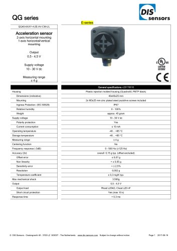
 QG40-KAXY-1,5E-AV-CM-UL
3 Pages
-
 QG40-KAXY-1,5E-AI-CM-UL
3 Pages
-
 QG40-KAXY-4,0E-AV-CM-UL
3 Pages
-
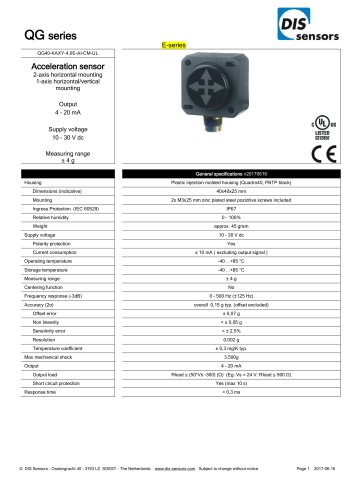 QG40-KAXY-4,0E-AI-CM-UL
3 Pages
-
 QG40-KAXY-16,0E-AV-CM-UL
3 Pages
-
 QG40-KAXY-16,0E-AI-CM-UL
3 Pages
-
 QG40N-KAXYh-1,5-AI-CM-UL
3 Pages
-
 QG40N-KAXYh-1,5-AV-CM-UL
3 Pages
-
 QG40N-KAXYh-4,0-AI-CM-UL
3 Pages
-
 QG40N-KAXYh-4,0-AV-CM-UL
3 Pages
-
 QG40N-KAXYh-16,0-AI-CM-UL
3 Pages
-
 QG40N-KAXYh-16,0-AV-CM-UL
3 Pages
-
 QG76N-SAXYZ-8-CANS-C(F)M-2d
2 Pages
-
 QG40-KD-090H-AV-CM-5V-UL
3 Pages
-
 QG40-KD-090E-AV-CM-5V-UL
3 Pages
-
 QG40-KD-090H-AI-CM-UL
3 Pages
-
 QG40-KD-090H-AV-CM-UL
3 Pages
-
 QG40-KD-090E-AV-CM-UL
3 Pages
-
 QG40-KD-030H-AV-CM-5V-UL
3 Pages
-
 QG40-KD-030E-AV-CM-5V-UL
3 Pages
-
 QG40-KD-030H-AI-CM-UL
3 Pages
-
 QG40-KD-030E-AI-CM-UL
3 Pages
-
 QG40-KD-030H-AV-CM-UL
3 Pages
-
 QG40-KD-030E-AV-CM-UL
3 Pages
-
 QG40-KD-010H-AV-CM-5V-UL
3 Pages
-
 QG40-KD-010E-AV-CM-5V-UL
3 Pages
-
 QG40-KD-010H-AI-CM-UL
3 Pages
-
 QG40-KD-010E-AI-CM-UL
3 Pages
-
 QG40-KD-010H-AV-CM-UL
3 Pages
-
 QG40-KD-010E-AV-CM-UL
3 Pages
-
 QG30-KI-090H-AV-K-5V
2 Pages
-
 QG30-KI-090H-AV-K
2 Pages
-
 QG30-KI-090H-AI-K
2 Pages
-
 QG30-KI-030H-AV-K-5V
2 Pages
-
 QG30-KI-030H-AV-K
2 Pages
-
 QG30-KI-030H-AI-K
2 Pages
-
 QG30-KI-010H-AV-K-5V
2 Pages
-
 QG30-KI-010H-AV-K
2 Pages
-
 QG30-KI-010H-AI-K
2 Pages
-
 QG76N-SIXv-360-CANS-C(F)M-2d
2 Pages
-
 QG65N-KIXv-360-CANS-C(F)M-2d
2 Pages
-
 QG76N-SDXYh-090-CAN-C(F)M
2 Pages
-
 QG65N-KDXYh-090-CAN-C(F)M
2 Pages
-
 QG76N-SDXYh-030-CAN-C(F)M
2 Pages
-
 QG65N-KDXYh-030-CAN-C(F)M
2 Pages
-
 QG65-KD-090H-CAN-C(F)M
2 Pages
-
 QG65-KD-030H-CAN-C(F)M
2 Pages
-
 QG65N-KIXv-360-CAN-C(F)M
2 Pages
-
 QG65-KD-030X-CAN-C(F)M-T
2 Pages
-
 QG65-KI-360X-CAN-C(F)M-T
2 Pages
-
 QG65-KI-360H-CAN-C(F)M
2 Pages
-
 QG40-KD-090E-AI-CM-UL
3 Pages
-
 QG76-SI-360H-AI-CM
2 Pages
-
 QG76-SI-360H-AV-CM
2 Pages
-
 QG76-SD-010H-AV-CM
2 Pages
-
 QG76-SD-010H-AI-CM
2 Pages
-
 QG65-KI-360H-AV-CM
2 Pages
-
 QG65-KI-360H-AI-CM
2 Pages
-
 QG65-KD-090H-AV-CM
2 Pages
-
 QG65-KD-090H-AI-CM
2 Pages
-
 QG65-KD-030H-AV-CM
2 Pages
-
 QG65-KD-030H-AI-CM
2 Pages
-
 QG65-KD-010H-AV-CM
2 Pages
-
 QG65-KD-010H-AI-CM
2 Pages
-
 QG40N-KIXv-360-SPI-PTS-5V
2 Pages
-
 QG40N-KIXv-360-SPI-PTS
2 Pages
-
 QG40N-KIXv-360-2AI-PT
2 Pages
-
 QG30-KI-090E-AV-K-5V
2 Pages
-
 QG30-KI-090E-AV-K
2 Pages
-
 QG30-KI-090E-AI-K
2 Pages
-
 QG30-KI-030E-AV-K-5V
2 Pages
-
 QG30-KI-030E-AI-K
2 Pages
-
 QG30-KI-030E-AV-K
2 Pages
-
 QG30-KI-010E-AV-K-5V
2 Pages
-
 QG30-KI-010E-AI-K
2 Pages
-
 QG40N-KDXYh-010-AV-CM-UL
3 Pages
-
 QG40N-KDXYh-030-AI-CM-UL
3 Pages
-
 QG40N-KDXYh-030-AV-CM-UL
3 Pages
-
 QG40N-KDXYh-090-AI-CM-UL
3 Pages
-
 QG40N-KDXYh-090-AV-CM-UL
3 Pages
-
 QG40N-KIXv-090-2AI-PT
2 Pages
-
 QG40N-KIXv-360-AI-CM-UL
3 Pages
-
 QG40N-KIXv-360-AV-CM-UL
3 Pages
-
 QG40N configurator
1 Pages
-
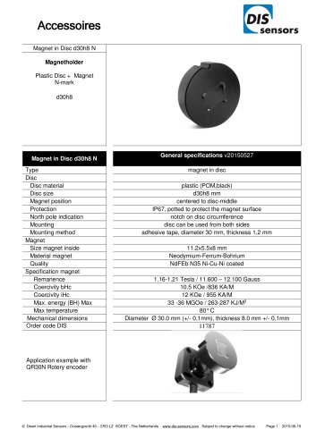
 Magnet in Disc d30h8 N
1 Pages
-
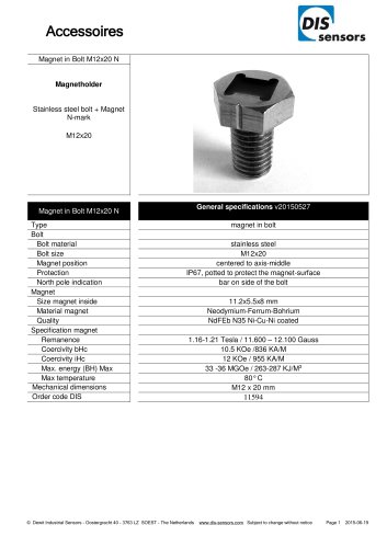
 Magnet in Bolt M12x20 N
1 Pages
-
 Cable USB to RS232 adapter
1 Pages
-
 Cable PUR 1x M12 Female 8p
2 Pages
-
 Cable PVC 1x M12 Female 5p
2 Pages
-
 DIS Sensors catalogue
12 Pages
-
 DIS Sensors leaflet 2014
2 Pages