- Catalogs
- Diodes Incorporated
- ZXCT21x
ZXCT21x
1 /15Pages

ZXCT21x
1 /15Pages
Catalog excerpts

ZXCT21x 26V, ZERO-DRIFT, HIGH-PRECISION CURRENT MONITOR Description The ZXCT21x series are high-precision current-shunt monitor with different choices of gain options to measure low-voltage drop (10mV) across a small shunt resistor with minimal error. This enables high accuracy of large current measurement and reduces a power loss caused by the measurement at common-mode voltages from -0.3V to 26V. OUT pin is a voltage proportional to the load current. It can then be processed with an ADC. There are six fixed gains available: 50, 75, 100, 200, 500, and 1000V/V respectively. This device is designed with zero-drift architecture and is manufactured by post trim technology to achieve low offset voltage, low gain drift and low gain error among full temperature range for precise measurement. The ZXCT21x operates from a single 2.7V to 26V power supply with a maximum of 100pA of supply current from -40°C to +125°C, and is offered in the SOT363 and U-QFN1418-10 package. Features • Supply Voltage Range: 2.7V to 26V • Temperature Range: -40°C to +125°C • Wide Common-Mode Range: -0.3V to 26V • Support Shunt Drops of 10mV Full-Scale • Gain Error (Maximum Overtemperature) ■ A and B Version: ±0.8% • Low Gain Error Drift: 10ppm/°C (max) • Rail-to-Rail Output Capacity • Choice of Gains: - ZXCT210: 200V/V - ZXCT211: 500V/V - ZXCT212: 1000V/V - ZXCT213: 50V/V - ZXCT214: 100V/V - ZXCT215: 75V/V • Package: 6-pin SOT363 and 10-pin U-QFN1418-10 • Totally Lead-Free & Fully RoHS Compliant (Notes 1 & 2) • Halogen and Antimony Free. “Green” Device (Note 3) • An automotive-compliant part is available under separate datasheet (ZXCT21 xQ) SOT363 Applications • Notebook computers • Server farms • Current sensing (high-side/low-side) • Battery charging and discharging • High-performance video cards • Industrial power supplies • Control systems Notes: 1. No purposely added lead. Fully EU Directive 2002/95/EC (RoHS), 2011/65/EU (RoHS 2) & 2015/863/EU (RoHS 3) compliant. 2. See https://www.diodes.com/quality/lead-free/ for more information about Diodes Incorporated's definitions of Halogen- and Antimony-free, "Green" and Lead-free. 3. Halogen- and Antimony-free "Green” products are defined as those which contain <900ppm bromine, <900ppm chlorine (<1500ppm total Br + Cl) and <1000ppm antimony compounds. December 2023 © 2023 Copyright Diodes Incorporated. All
Open the catalog to page 1
ZXCT21x Typical Applications Circuit Part Number Supply Rsense Load Reference Voltage December 2023 © 2023 Copyright Diodes Incorporated. All Rights Reserved.
Open the catalog to page 2
Note: 7. Refer to the typical application circuit. December 2023 © 2023 Copyright Diodes Incorporated. All Rights Reserved.
Open the catalog to page 3
ZXCT21x Electrical Characteristics (Ta = +25°C, Vs = 5V, Vin+ = 12V, Vsense = Vin+ - Vin-, and Vref = Vs/2, unless otherwise specified.) Notes: 8. RTI stands for referred to input. For ZXCT210 and ZXCT213, the long-term stability of Vos are 100pV and 150pV respectively which are defined as maximum Vos drift during high temperature life test 1000 hours with Ta = +1250C. The Vos drift is not a linear function of time, and is greater initially and diminishes over time. This parameter is not in production test, but guaranteed by design. 9. This parameter value is guaranteed by characterization, but...
Open the catalog to page 4
ZXCT21x Typical Performance Characteristics Input Offset Voltage(uV) Input Offset Voltage (μV) Figure 1. Offset Voltage vs. Temperature Figure 2. Common-Mode Rejection Ratio vs. Temperature Figure3.3. Gain vs. Frequency Figure Gainvs Frequency Figure 4. Power-Supply Rejection Ratio vs. Frequency Figure4. Power-SupplyRejectionRatiovs Frequency Output-Voltage Swing(V) Output Voltage Swing(V) Output Current(mA) Figure 6. Output Voltage Swing vs. Output Current Output-Voltage Swing Figure5. Common-ModeRejectionRatiovs Frequency Figure 5. Common-Mode Rejection Ratio vs. Frequency December 2023 © 2023...
Open the catalog to page 5
ZXCT21x Typical Performance Characteristics (continued) Input Bias Current (μA) Input Bias Current(uA) Output-Voltage Swing(V) Output Voltage Swing(V) Output Current(mA) Common-Mode Voltage(V) Figure 8. Input Bias Current vs. Common-Mode Voltage Figure 7. Output-Voltage Swing vs. Output Current Output Voltage Input Bias Current (μA) Input Bias Current(uA) Input Bias Current (μA) Input Bias Current(uA) Common-Mode Voltage(V) Figure 9. Input Bias Current vs. Common-Mode Voltage With Supply Voltage=0V(Shutdown) =0 Figure 10. Input Bias Current vs. Temperature December 2023 © 2023 Copyright Diodes...
Open the catalog to page 6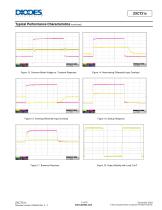
ZXCT21x Typical Performance Characteristics (continued) Figure 13. Common-Mode Voltage vs. Transient Response Figure 14. Noninverting Differential Input Overload Figure 15. Inverting Differential Input Overload Figure 16. Startup Response Figure 17. Brownout Recovery Figure 18. Output Stability with Load 2.2nF December 2023 © 2023 Copyright Diodes Incorporated. All Rights Reserved.
Open the catalog to page 7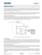
ZXCT21x Application Information The ZXCT21x series are 26V, common-mode, zero-drift, current-sensing amplifiers that can be used in both low-side and high-side configurations. These specially-designed, current-sensing amplifiers are able to accurately measure voltages developed across current-sensing resistors on common-mode voltages that far exceed the supply voltage powering the device. Current can be measured on input voltage rails as high as 26V while the device can be powered from supply voltages as low as 2.7V. The ZXCT21x current-sense amplifiers can be configured for both low-side and...
Open the catalog to page 8
ZXCT21x Application Information (continued) Figure 20. Bidirectional Current Sensing with an External Voltage Reference Circuit Input Filtering Input filtering may be needed to limit the bandwidth of signals or to add protection against transients that may be generated as the result of shunt inductance. Input filter resistors associates resistance mismatch between them can adversely affect gain, CMRR, and VOS. The effect on VOS is partly due to input bias currents as well. As a result, the value of the input resistors should be limited to 10Ω or less. Ideally, select the capacitor to exactly...
Open the catalog to page 9All Diodes Incorporated catalogs and technical brochures
 ZXCT21x
2 Pages
 PI2MEQX2503
16 Pages
 AP43781
2 Pages
 APR3401
9 Pages
 AP3306
13 Pages
 AP3306
2 Pages
 AP43771H
9 Pages
 PAM8907
10 Pages
 AP22953
12 Pages
 PI6LC58S1101
17 Pages
 PI3EQX12902E
1 Page
 AP22653Q
13 Pages
 PAM8965
25 Pages
 Protection Products
2 Pages
 LOGIC PRODUCTS
20 Pages
 MOSFETS
20 Pages
 automotive products
20 Pages
 PRODUCT OVERVIEW
2 Pages
 Logic single gate 74AHC1G00
8 Pages
 AMR sensor angular ZMT32
10 Pages
 Audio amplifiers PAM8001
17 Pages
 Off-line LED drivers AL9910
15 Pages
 Operational amplifiers AP358
16 Pages
 Buck converter AP1501
12 Pages
 MOSFETs N Channel DMG1012T
6 Pages
 Bipolar transistor 2DA2018
5 Pages
 Schottky diodes 1N5711WS
3 Pages
 SENSORS AND MOTOR CONTROL
12 Pages
 LED Driver
16 Pages
 STANDARD LINEAR AND LOGIC
12 Pages
 Power Management
12 Pages
 BIPOLAR TRANSISTORS
24 Pages
 SBR®
SBR®12 Pages
 MOSFETs
16 Pages


Archived catalogs
 Diodes Product Design Guide
173 Pages

- Temperature probe
- Resistance temperature sensor
- Proximity switch
- Technology switch
- Signal amplifying integrated circuit
- Transceiver module
- Motor controller
- Rotary electric switch
- RTD temperature sensor
- Power amplifying integrated circuit
- DC motor controller
- Transistor module
- Touch switch
- Signal conditioner
- Magnetic proximity sensor
- Rectifier diode
- DC amplifier
- On/off switch
- Radio transceiver module