
- Catalogs
- Diodes Incorporated
- PI6LC58S1101

- Products
- Catalogs
- News & Trends
- Exhibitions
PI6LC58S1101

PI6LC58S1101
- Operates at 3.3V supply voltage.
- Supports crystal/CMOS and differential inputs at 25MHz/50MHz.
- Selectable output frequencies and signaling types (LVPECL or LVDS).
- Very low RMS phase jitter (0.08ps typical at 156.25MHz).
- Excellent phase noise performance (-145dBc/Hz at 100kHz offset).
- Supports industrial temperature ranges from -40°C to 85°C.
- Complies with RoHS and is lead-free, halogen, and antimony-free.
Catalog excerpts

A product Line of Diodes Incorporated Lead-free Green PI6LC58S1101 11 Outputs HiFlex™ Ethernet Network Clock Generator The PI6LC58S1101 is very low jitter clock generator target for applications that demand extremely low phase noise, such as 10GbE, 40GbE, 100GbE, and 400GbE. It uses Diodes' proprietary LC VCO-based PLL design to achieve an optimum combination of those popular networking clock frequencies and low phase noise performance along with high power supply noise rejection. ÎÎ Crystal/CMOS Input: 25MHz/50MHz ÎÎ Differential Input: 25MHz/50MHz ÎÎ Selectable Output Frequencies ÎÎ Four Output Banks with Selectable Output Signaling: LVPECL or LVDS low RMS Phase jitter: 0.08ps (typ.), 156.25MHz (10kHz to 20MHz) ÎÎ Excellent phase noise: -145dBc/Hz, 156.25MHz at 100kHz offset ÎÎ Power Supply Noise Rejection: -55dBc ÎÎ Industrial Temperature Support: -40°C to 85°C ÎÎ Totally Lead-Free & Fully RoHS Compliant (Notes 1 & 2) ÎÎ Halogen and Antimony Free. “Green” Device (Note 3) ÎÎ For automotive applications requiring specific change control (i.e. parts qualified to AEC-Q100/101/200, PPAP capable, and manufactured in IATF 16949 certified facilities), please contact us or your local Diodes representative. https://www.diodes.com/quality/product-definitions/ ÎÎ Packaging (Pb-free & Green): 64-lead 9mm × 9mm TQFN ÎÎ Very The PI6LC58S1101 has four output banks which can be configured independently for different frequencies and different output signaling types based on control pins. The pin control method provides an easy way to configure the device at the hardware level. Block Diagram Bank A 4 DIVA CONTROL REGISTERS Notes: 1. No purposely added lead. Fully EU Directive 2002/95/EC (RoHS), 2011/65/EU (RoHS 2) & 2015/863/EU (RoHS 3) compliant. 2. See https://www.diodes.com/quality/lead-free/ for more information about Diodes Incorporated’s definitions of Halogen- and Antimony-free, "Green" and Lead-free. 3. Halogen- and Antimony-free "Green” products are defined as those which contain <900ppm bromine, <900ppm chlorine (<1500ppm total Br + Cl) and <1000ppm antimony compounds. PI6LC58S1101
Open the catalog to page 1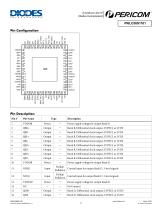
A product Line of Diodes Incorporated Power supply voltage for output Bank B Bank B, Differential clock output, LVPECL or LVDS Bank B, Differential clock output, LVPECL or LVDS Bank B, Differential clock output, LVPECL or LVDS Bank B, Differential clock output, LVPECL or LVDS Bank B, Differential clock output, LVPECL or LVDS Bank B, Differential clock output, LVPECL or LVDS Bank B, Differential clock output, LVPECL or LVDS Bank B, Differential clock output, LVPECL or LVDS Power supply voltage for output Bank B Pullup/ Control input for output Bank D. 3-level signals Pulldown Pullup/ Control input...
Open the catalog to page 2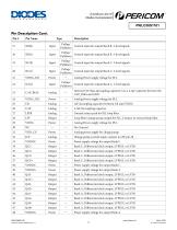
A product Line of Diodes Incorporated Pullup/ Control input for output Bank B. 3-level signals Pulldown Pullup/ Control input for output Bank B. 3-level signals Pulldown Pullup/ Control input for output Bank C. 3-level signals Pulldown Pullup/ Control input for output Bank C. 3-level signals Pulldown Internal VCO bias decoupling capacitor. Use a 4.7μF capacitor between the CAP_BIAS and GND Analog Power supply voltage for PLL 1uF decoupling capacitor between CR amd VDDA Ground return path for PLL loop filter Loop filter/ charge pump output for PLL. Connect to external loop filter Analog Power...
Open the catalog to page 3
A product Line of Diodes Incorporated Description Selects input reference source. LVCMOS interface levels. Pulldown 0 = Crystal input on pins X_IN, X_Out (default) 1 = Reference clock input on pins IN+, IN- Pullup/ Differential clock input Pulldown Internal resistor bias to VDD_CLK/2 Pulldown Differential clock input Crystal oscillator circuit decoupling capacitor. Use a 4.7μF capacitor between the CAP_XTAL and the GND terminals. Crystal in, the input also supports being driven by a single-ended crystal oscillator or reference clock Analog power supply voltage for the crystal oscillator Power...
Open the catalog to page 4
A product Line of Diodes Incorporated PI6LC58S1101 Input MUX Selection IN_SEL Input Source Crystal Input (X_IN, X_OUT) Input Frequency Selection FREQ_IN Input Source Bank A Differential Output Control NA[1] Output Types Power Down, both outputs of the differential output pair will drive a logic-high level Bank B Differential Output Control NB[1] Output Types Power Down, both outputs of the differential output pair will drive a logic-high level March 2020 Diodes Incorporated
Open the catalog to page 5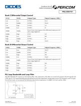
A product Line of Diodes Incorporated PI6LC58S1101 Bank C Differential Output Control NC[1] Output Types Power Down, both outputs of the differential output pair will drive a logic-high level Bank D Differential Output Control ND[1] Output Types Power Down, both outputs of the differential output pair will drive a logic-high level PLL Loop Bandwidth and Loop Filter The PI6LC58S1101 PLL requires an external loop filter. The components of the filter are connected in between the ICP (pin32) and LFFR (pin27). PLL loop bandwidth generally depends on the loop components, charge pump current, PFD frequency,...
Open the catalog to page 6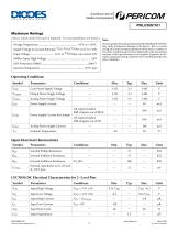
A product Line of Diodes Incorporated Note: Stresses greater than those listed under MAXIMUM RATINGS may cause permanent damage to the device. This is a stress rating only and functional operation of the device at these or any other conditions above those indicated in the operational sections of this specification is not implied. Exposure to absolute maximum rating conditions for extended periods may affect reliability. Operating Conditions Symbol Core Power Supply Voltage Output Power Supply Voltage Analog Power Supply Voltage Power Supply Current All outputs loaded, Diff. Outputs are LVPECL...
Open the catalog to page 7
A product Line of Diodes Incorporated PI6LC58S1101 LVCMOS DC Electrical Characteristics for 3- Level Pins Symbol Input High Voltage Input Middle Voltage Input High Current Input Middle Current Differential Input DC Characteristics Symbol Input High Voltage Input Bias Voltage Input Differential Swing Differential peak to peak Crystal Characteristic Parameters Equivalent Series Resistance Load Capacitance, 50MHz crystal Load Capacitance, 25MHz crystal Shunt Capacitance Drive Level Cload Cshunt Note: 1. ESR value is dependent upon frequency of oscillation LVPECL Output DC Characteristics(1) Symbol...
Open the catalog to page 8All Diodes Incorporated catalogs and technical brochures
 ZXCT21x
2 Pages
 ZXCT21x
15 Pages
 PI2MEQX2503
16 Pages
 AP43781
2 Pages
 APR3401
9 Pages
 AP3306
13 Pages
 AP3306
2 Pages
 AP43771H
9 Pages
 PAM8907
10 Pages
 AP22953
12 Pages
 PI3EQX12902E
1 Page
 AP22653Q
13 Pages
 PAM8965
25 Pages
 Protection Products
2 Pages
 LOGIC PRODUCTS
20 Pages
 MOSFETS
20 Pages
 automotive products
20 Pages
 PRODUCT OVERVIEW
2 Pages
 Logic single gate 74AHC1G00
8 Pages
 AMR sensor angular ZMT32
10 Pages
 Audio amplifiers PAM8001
17 Pages
 Off-line LED drivers AL9910
15 Pages
 Operational amplifiers AP358
16 Pages
 Buck converter AP1501
12 Pages
 MOSFETs N Channel DMG1012T
6 Pages
 Bipolar transistor 2DA2018
5 Pages
 Schottky diodes 1N5711WS
3 Pages
 SENSORS AND MOTOR CONTROL
12 Pages
 LED Driver
16 Pages
 STANDARD LINEAR AND LOGIC
12 Pages
 Power Management
12 Pages
 BIPOLAR TRANSISTORS
24 Pages
 SBR®
SBR®12 Pages
 MOSFETs
16 Pages


Archived catalogs
 Diodes Product Design Guide
173 Pages

- Temperature probe
- Resistance temperature sensor
- Signal amplifying integrated circuit
- Motor controller
- Transceiver module
- Rotary electric switch
- RTD temperature sensor
- Power amplifying integrated circuit
- DC motor controller
- Transistor module
- Signal conditioner
- Rectifier diode
- DC amplifier
- On/off switch
- Radio transceiver module
- Brushless motor control
- Avalanche diode
- Switching transistor
- Electronic amplifier