AP3306
1 /13Pages

AP3306
1 /13Pages
Catalog excerpts

Lead-free Green Description The DIODES™ AP3306 is a highly integrated Active Clamp Flyback (ACF) controller optimally designed for offline power supplies to meet ultra-low standby power, high power density, and comprehensive protection requirements. The controller realizes non-complimentary high-low-side control mechanisms to achieve Leakage Energy Recycling and Zero Voltage Switching (ZVS) for supreme-efficiency performance. The AP3306 provides a high-voltage start-up function through the HV pin, reducing standby loss. Moreover, the AP3306 integrates a VCCL LDO circuit, allowing the LDO to regulate the wide range VCCL to an acceptable value. This makes the AP3306 an ideal candidate for wide-range output-voltage applications, such as USB-PD. The built-in frequency dithering function greatly eases EMI design as well. At no load or light load, the IC will enter burst mode to minimize standby power consumption. The minimum switching frequency (about 22kHz) is set to avoid audible noise. When the load increases, the IC will enter ACF mode with frequency foldback to improve system efficiency and EMI performance. The maximum switching frequency (about 130kHz or 200kHz optional) is set to clamp the switching frequency to reduce switching power loss. Comprehensive protection features are included, such as Brown-Out Protection (BNO), Cycle-by-Cycle Overcurrent Protection (OCP), VCC Overvoltage Protection (VOVP), Secondary-Side Output OVP (SOVP) and UVP (SUVP), internal Overtemperature Protection (OTP), Overload Protection (OLP), and Pin Fault Protection. Features Applications • Active Clamp Flyback Topology with Recycled Leakage Energy and Pseudo Zero Voltage Switching Functions • High-Voltage Startup • Embedded VCC LDO for VCCL Pin to Guarantee Wide Range Output Voltage • Non-Audible-Noise Quasi-Resonant Control • Soft Start During Startup Process • Frequency Foldback for High Average Efficiency • Secondary Winding Short Protection with FOCP • Frequency Dithering for Reducing EMI • X-CAP Discharge Function • Useful Pin Fault Protection • FB/Opto-Coupler Open/Short Protection • Comprehensive System Protection Features: ■ VCC Overvoltage Protection (VOVP) ■ Overload Protection (OLP) ■ Brown-Out Protection (BNO) ■ Secondary-Side OVP (SOVP) and UVP (SUVP) • Packaged in the SO-10 (Type A1) • Totally Lead-Free & Fully RoHS Compliant (Notes 1 & 2) • Halogen and Antimony Free. “Green” Device (Note 3) • For automotive applications requiring specific change control (i.e. parts qualified to AEC-Q100/101/200, PPAP capable, and manufactured in IATF 16949 certified facilities), please contact us or your local Diodes representative. https://www.diodes.com/quality/product-definitions/ • Smartphone quick chargers • Notebook computer adapters • High-Power density adapters/chargers: 30W/inch3 • Compact switching AC-DC adapter/charger • Suitable for variable output voltage applications (USB PD, QC, SCP, VSCP, VOOC, AFC, etc.) • ATX/BTX auxiliary power applications • Set-top box (STB) power supplies • Open-frame switching power supplies Notes: 1. No purposely added lead. Fully EU Directive 2002/95/EC (RoHS), 2011/65/EU (RoHS 2) & 2015/863/EU (RoHS 3) compliant. 2. See https://www.diodes.com/quality/lead-free/ for more information about Diodes Incorporated’s definitions of Halogen- and Antimony-free, "Green" and Lead-free. 3. Halogen- and Antimony-free "Green” products are defined as those which contain <900ppm bromine, <900ppm chlorine (<1500ppm total Br + Cl) and <1000ppm antimony compounds.
Open the catalog to page 1
Typical Applications Circuit Pin Descriptions Pin Name
Open the catalog to page 2
Functional Block Diagram Figure 2. Functional Block Diagram of AP3306
Open the catalog to page 3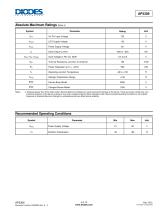
Absolute Maximum Ratings (Note 4) Symbol Notes: 4. Stresses greater than those listed under Absolute Maximum Ratings can cause permanent damage to the device. These are stress ratings only, and functional operation of the device at these or any other conditions beyond those indicated under Recommended Operating Conditions is not implied. Exposure to Absolute Maximum Ratings for extended periods can affect device reliability. Recommended Operating Conditions Symbol
Open the catalog to page 4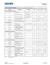
Electrical Characteristics (@ Ta= +25°C, Vccl = 18V, unless otherwise specified.) Note: 5. Guaranteed by design.
Open the catalog to page 5
Electrical Characteristics (@ Ta = +25°C, Vccl = 18V, unless otherwise specified.) (continued) Note: 5. Guaranteed by design. 6. AP3306 controls a PMOS switch by driving the gate of the PMOS with GDH and connecting the source of the PMOS to VCCL. Thus, the spec. Vgdh-l shows the small voltage difference between VCCL pin and GDH pin for turning off the PMOS, and the spec. Vgdh-h shows the large voltage difference for turning on. Furthermore, the tGDH-RISE measures the increasing of voltage difference between VCCL pin and GDH pin and the tGDH-FALL measures the decreasing of voltage difference between...
Open the catalog to page 6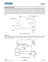
Operation Description Diodes Incorporated’s Smart Active Clamp Control Strategy: Valley Switching & Zero Voltage Switch (ZVS) Multiple Operation Modes. The AP3306’s patented control strategy allows the Active Clamp Fly-back system to operate on valley switching or ZVS according to the input voltage. When operating under low line input, the valley switching can naturally achieve ZVS and the leakage inductance energy will be transferred to output through the high side PMOSFET and CSN. When operating under high line input, the ZVS mode activated with perfect jitter whilst balancing system efficiency...
Open the catalog to page 7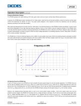
Operation Description (continued) Frequency Modulation Strategy The AP3306 operates with valley switching, ZVS mode, green mode, and burst mode to achieve high-efficiency performance. In general, the AP3306 power system operates with first “valley status” under low-line and full-load conditions, where the maximum primary peak current and transformer flux density can occur. The power system designer is thus required to choose the transformer size and switching frequency according to this worst-case condition. With output load decreasing from full load in the first “valley status”, the switching...
Open the catalog to page 8All Diodes Incorporated catalogs and technical brochures
 ZXCT21x
2 Pages
 ZXCT21x
15 Pages
 PI2MEQX2503
16 Pages
 AP43781
2 Pages
 APR3401
9 Pages
 AP3306
2 Pages
 AP43771H
9 Pages
 PAM8907
10 Pages
 AP22953
12 Pages
 PI6LC58S1101
17 Pages
 PI3EQX12902E
1 Page
 AP22653Q
13 Pages
 PAM8965
25 Pages
 Protection Products
2 Pages
 LOGIC PRODUCTS
20 Pages
 MOSFETS
20 Pages
 automotive products
20 Pages
 PRODUCT OVERVIEW
2 Pages
 Logic single gate 74AHC1G00
8 Pages
 AMR sensor angular ZMT32
10 Pages
 Audio amplifiers PAM8001
17 Pages
 Off-line LED drivers AL9910
15 Pages
 Operational amplifiers AP358
16 Pages
 Buck converter AP1501
12 Pages
 MOSFETs N Channel DMG1012T
6 Pages
 Bipolar transistor 2DA2018
5 Pages
 Schottky diodes 1N5711WS
3 Pages
 SENSORS AND MOTOR CONTROL
12 Pages
 LED Driver
16 Pages
 STANDARD LINEAR AND LOGIC
12 Pages
 Power Management
12 Pages
 BIPOLAR TRANSISTORS
24 Pages
 SBR®
SBR®12 Pages
 MOSFETs
16 Pages


Archived catalogs
 Diodes Product Design Guide
173 Pages

- Bourn And Koch temperature sensor
- Bourn And Koch resistance temperature sensor
- Bourn And Koch proximity sensor
- Technology switch
- Bourn And Koch signal amplifier
- Bourn And Koch transceiver
- Motor controller
- Rotary electric switch
- RTD temperature sensor
- Bourn And Koch power amplifier
- DC motor controller
- Bourn And Koch transistor
- Touch switch
- Signal conditioner
- Bourn And Koch magnetic proximity sensor
- Rectifier diode
- DC amplifier
- On/off switch
- Bourn And Koch radio transceiver