- Catalogs
- Diodes Incorporated
- AMR sensor angular ZMT32
AMR sensor angular ZMT32
1 /10Pages

AMR sensor angular ZMT32
1 /10Pages
Catalog excerpts

ZMT32 Magnetic Field Angle Sensor Description The ZMT32 is a thin film permalloy magnetic field sensor, which contains two galvanic isolated Wheatstone Bridges for high precision angle measurement applications under low field conditions. This angle sensor is based on the anisotropic magnetoresistive effect (AMR). The two internal (VCC1, VCC2) bridges enclose a relative sensitive angle of 45 degrees. The input field is a rotating magnetic field in the chip plane (parallel to the surface of package). This rotating field will make available two independent sinusoidal output signals with the following relationship The precise ZMT32 works with low field applications (Hrot= 8 to 25kA/m), much lower than similar devices. The ultimate output signal quality depends on the external magnetic material and on the mechanical realization. The ZMT32 is a passive part and the ArcTangent interpolation needs external signal processing. Typical areas of application are angle and speed measurement. where α = angle between sensor axis and field direction contactless angle measurement up to 180° angle and angular velocity measuring systems flexible measuring solutions for moved systems absolute angle and angle change stable operation over long time automotive electronic (steering, control, pedal positioning, etc high temperature range up to +160°C contactless rotary switches and potentiometer automatic adjustment Ordering Information Device Reel size (Inches) Device marking Issue 1 - June 2008 © Zetex Semiconductors plc 2008
Open the catalog to page 1
ZMT32 Absolute maximum ratings Parameter Supply Voltages Single Bridge Current Operating Temperature Range Storage Temperature Range Recommended operating conditions Symbol Applied Magnetic Field Strength Issue 1 - June 2008 © Zetex Semiconductors plc 2008 Supply Voltages
Open the catalog to page 2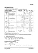
ZMT32 Electrical characteristics General test conditions (unless otherwise noted) TA= +23±5oC, VCC1=VCC2 = +5V, HROT=25kA/m(†), k=100•(VPO1/VPO2) with VCC1=VCC2 UNIT mV/V/deg Output offset voltage TC of peak to peak output swing or Peak to peak output swing ∆VO2/VCC2A TCVOB Bridge resistances PARAMETER Sensitivities (zero crossing) Peak Output Voltages VPO1 or VPO2 (sinusoidal signals) k Amplitude bridge matching Temperature coefficient of TCk amplitude bridge matching RB1 TC of output offset voltage Angular hysteresis Isolation Bridge Current Angular Inaccuracy NOTES: (*) Typical values apply...
Open the catalog to page 3
RB(Tn) is the bridge resistance at temperature Tn where VOFF(Tn) is the output offset voltage at temperature Tn Magnetic field tests For these tests a rotating magnetic field is generated and the output signals of both bridges are measured at four different field angles for right rotation as well as for left rotation. Using these measured output signals the diameter and the center coordinates of the best circle are calculated. They correspond to the output voltage range and the offset voltage. Furthermore the field angles for both rotation directions and angular hysteresis are calculated ⎛V ⎞...
Open the catalog to page 4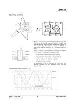
When a common-magnetic field is applied through the ZMT32 the 2 internal magneto-resistive bridges are affected slightly differently due to their 45° rotation to one another. This 45° rotation enables the ZMT32 to determine angular position, of a rotating magnetic field. When a rotating magnetic field is applied to the ZMT32 it will output 2 sinusoidal voltages that are: proportional to the field strength applied proportional to the supply voltage applied, rotating at twice the angular position 90° apart (as seen below). By taking the arcTan of the ratio of VO2 to VO1 the angular position of...
Open the catalog to page 5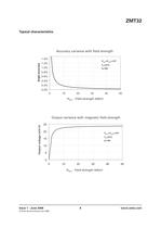
Accuracy variance with field strength Angle accuracy HROT - Field strength (kA/m) Output variance with magnetic field strength 25 20 HROT - Field strength (kA/m) Issue 1 - June 2008 © Zetex Semiconductors plc 2008
Open the catalog to page 6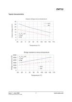
Output voltage versus temperature Bridge resistance versus temperature 6000 VCC1=VCC2=+5V Issue 1 - June 2008 © Zetex Semiconductors plc 2008
Open the catalog to page 7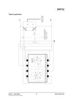
fixed 45 degree phase difference between outputs 1 and 2 result of angle measurement Typical application
Open the catalog to page 8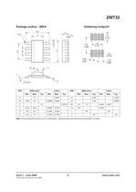
Soldering footprint Note: Controlling dimensions are in millimeters. Approximate dimensions are provided in inches Issue 1 - June 2008 © Zetex Semiconductors plc 2008
Open the catalog to page 9
ZMT32 Definitions Product change Zetex Semiconductors reserves the right to alter, without notice, specifications, design, price or conditions of supply of any product or service. Customers are solely responsible for obtaining the latest relevant information before placing orders. Applications disclaimer The circuits in this design/application note are offered as design ideas. It is the responsibility of the user to ensure that the circuit is fit for the user’s application and meets with the user’s requirements. No representation or warranty is given and no liability whatsoever is assumed by...
Open the catalog to page 10All Diodes Incorporated catalogs and technical brochures
 ZXCT21x
2 Pages
 ZXCT21x
15 Pages
 PI2MEQX2503
16 Pages
 AP43781
2 Pages
 APR3401
9 Pages
 AP3306
13 Pages
 AP3306
2 Pages
 AP43771H
9 Pages
 PAM8907
10 Pages
 AP22953
12 Pages
 PI6LC58S1101
17 Pages
 PI3EQX12902E
1 Page
 AP22653Q
13 Pages
 PAM8965
25 Pages
 Protection Products
2 Pages
 LOGIC PRODUCTS
20 Pages
 MOSFETS
20 Pages
 automotive products
20 Pages
 PRODUCT OVERVIEW
2 Pages
 Logic single gate 74AHC1G00
8 Pages
 Audio amplifiers PAM8001
17 Pages
 Off-line LED drivers AL9910
15 Pages
 Operational amplifiers AP358
16 Pages
 Buck converter AP1501
12 Pages
 MOSFETs N Channel DMG1012T
6 Pages
 Bipolar transistor 2DA2018
5 Pages
 Schottky diodes 1N5711WS
3 Pages
 SENSORS AND MOTOR CONTROL
12 Pages
 LED Driver
16 Pages
 STANDARD LINEAR AND LOGIC
12 Pages
 Power Management
12 Pages
 BIPOLAR TRANSISTORS
24 Pages
 SBR®
SBR®12 Pages
 MOSFETs
16 Pages


Archived catalogs
 Diodes Product Design Guide
173 Pages

- Temperature probe
- Resistance temperature sensor
- Proximity switch
- Technology switch
- Signal amplifying integrated circuit
- Transceiver module
- Motor controller
- RTD temperature sensor
- Power amplifying integrated circuit
- DC motor controller
- Diode
- Transistor module
- Touch switch
- Signal conditioner
- Magnetic proximity sensor
- Rectifier diode
- DC amplifier
- On/off switch
- Radio transceiver module