W8010
1 /4Pages
W8010
1 /4Pages
Catalog excerpts
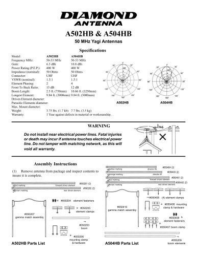
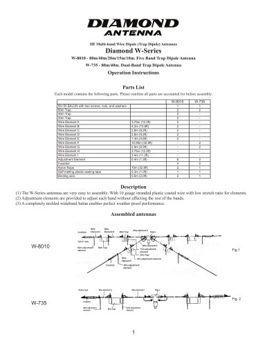
HF Multi-band Wire Dipole (Trap Dipole) Antennas Diamond W-Series W-8010 - 80m/40m/20m/15m/10m. Five Band Trap Dipole Antenna W-735 - 80m/40m. Dual-Band Trap Dipole Antenna Operation Instructions Parts List Each model contains the following parts. Please confirm all parts are accounted for before assembly. BU-50 BALUN with two screws, nuts, and washers 80m Trap 40m Trap 20m Trap Wire Element A Wire Element B Wire Element C Wire Element D Wire Element E Wire Element F Wire Element G Wire Element H Wire Element I Adjustment Element Insulator Nylon Rope Self-melting plastic sealing tape Binding wire (1) The W-Series antennas are very easy to assemble. With 10 guage stranded plastic coated wire with low stretch ratio for elements. (2) Adjustment elements are provided to adjust each band without affecting the rest of the bands. (3) A completely molded wideband balun enables perfect weather proof performance. Assembled antennas IInsulator nsulator Wire Wire Element C Element Wire Wire Element B Element element A Wire element Wire ylon rope rope Nylon adjustment 80m adjustment element element Wire element element D Wire adjustment 15m adjustment element element Trap 20m Trap Wire Wire Element E Element Insulator Insulator Nylon N ylon rope rope Wire element element G Wire adjustment element element 10m adjustment adjustment 20m adjustment element element Wire Wire element element F Insulator Insulator adjusmen 80m adjusment element element 40m adjustment adjustment element element
Open the catalog to page 1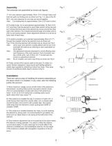
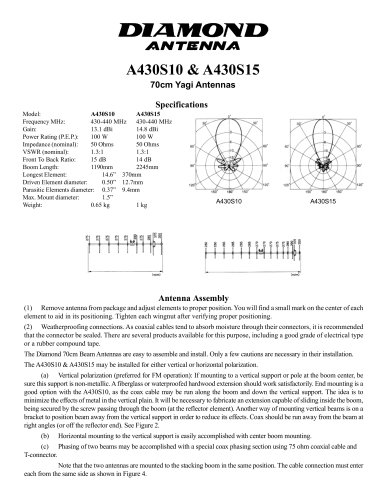
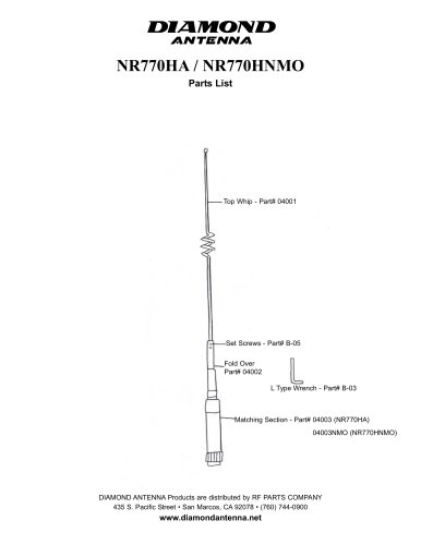
The antennas are assembled as shown per figures. 1. Turn wire element approximately 20cm (7.9”) through balun and bind two parts by binding wire as shown per Fig.1. In case of the W8010, two wire elements for one side are bound together. Note: Cut binding wire for approximately 10cm (3.9”) each to bind. 2. To install a trap, turn a wire element approximately 15-16cm (5.9”6.3”) and then hook the element to wire holder section of the trap and turn crimped terminal side of the element four times around the other side of the element. Put crimped terminal through wire holder and fix with nut and spring...
Open the catalog to page 2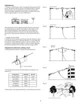
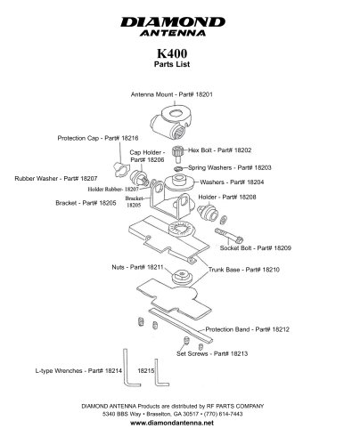
1. Prepare a VSWR power meter for applicable frequencies and RF power, and set the meter as shown in the following figure. Practice test transmission for the adjustment as short time and least RF power as possible. (Maximum power rating in canstant wave (CW) mode is approximately 1/3 of one in SSB mode.) VSWR power meter V Start adjustment from the highest operating frequency downward by cutting adjustment element, both sides in same length, to desired resonant frequency, least VSWR return at the frequency. Since cutting the element in excess may skip desired frequency and result in losing resonant...
Open the catalog to page 3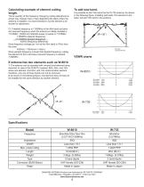
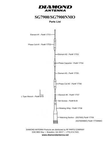
*Since quantity of the frequency change by cutting adjustment element may change more or less depending the place where the antenna is installed, it is recommended to cut the element a bit shorter for adjustment. Cf. If desired frequency is 7.052MHz at the 40m band and present resonant frequency when the antenna is initially installed is 7.010MHz, VSWR and reflected power is lowest in 7.010MHz: 7.052MHz (desired frequency) Since frequency change per 1cm at the 40m band is 7KHz from the chart. Since present frequency is lower than desired frequency, cutting the element for 6cm will make resonant...
Open the catalog to page 4