A502HB
1 /4Pages

A502HB
1 /4Pages
Catalog excerpts
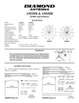
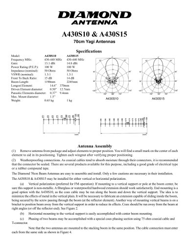
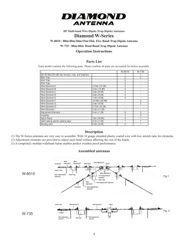
A502HB & A504HB 50 MHz Yagi Antennas Specifications Model: A502HB A504HB Frequency MHz: 50-53 MHz 50-53 MHz Gain: 6.3 dBi 10.8 dBi Power Rating (P.E.P.): 400 W 400 W Impedance (nominal): 50 Ohms 50 Ohms Connector: UHF UHF VSWR (nominal): 1.5:1 1.5:1 Element Phasing: 2 4 Front To Back Ratio: 15 dB 12 dB Boom Length: 2.5 ft. (750mm) 10.66 ft. (3250mm) Longest Element: 9.84 ft. (3000mm) 9.84 ft. (3000mm) Driven Element diameter: Parasitic Elements diameter: Max. Mount diameter: Weight: 3.75 lbs. (1.7 kb) 7.7 lbs. (3.5 kg) Warranty: 1 Year against defects in material or workmanship. WARNING Do not install near electrical power lines. Fatal injuries or death may incur if antenna touches electrical power line. Do not tamper with matching network, as this will void all warranty. Assembly Instructions brown marking forward driven element rear driven element yellow marking orange marking brown marking forward driven element (1) Remove antenna from package and inspect contents to insure it is complete. rear driven element mounting clamp & hardware #050410 gamma match assembly #050207 gamma match assembly #050206 mounting clamp & hardware
Open the catalog to page 1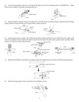
(2) Loosen element clamp wing nuts on the Boom and adjust into correct mounting position. (A504HB Only ~ Clamp Boom sections together with proper mounting hardware.) element clamp boom boom (3) Match elements to element clamps with similar color. Fit elements into mounting clamps so element hole fits through clamp extension. When elements are in proper position, tighten wing nut. element element clamp element clamp extension boom (4) Install gamma match assembly with red label into position matching red label on boom. Match the hole on Boom with extension on gamma match assembly and fasten wing...
Open the catalog to page 2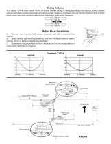
Tuning Antenna With quality VSWR meter, check VSWR for proper antenna tuning. If tuning adjustments are required, loosen element fasteners and slide in similar increments until desired center frequency is obtained. Moving element fasteners closer to boom lowers center frequency and moving them away from boom raises center frequency. Before Final Installation A. Use coax seal to protect both antenna connection and cable connection from weather. B. Spray antenna and mounting hardware with non-conductive acrylic paint to increase the life of antenna and mounting hardware. C. Recommend using removable...
Open the catalog to page 3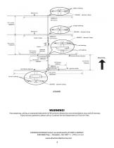
yellow marking director #2 #050405 element clamp (98.4 inches) (55.1 inches) orange marking boom clamp element fasteners forward driven element rear driven element gamma match brown marking Any tampering, cutting, or attempted adjustment of this antenna beyond our recommendations may void all warranty. If you have any questions, please call our Customer Service Department at (770) 614-7443. DIAMOND ANTENNA Products are distributed by RF PARTS COMPANY 5340 BBS Way | Braselton, GA 30517 | (770) 614-7443
Open the catalog to page 4