- Catalogs
- Diamond Systems
- har82c54
har82c54
1 /17Pages

har82c54
1 /17Pages
Catalog excerpts
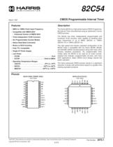
CMOS Programmable Interval Timer • 8MHz to 12MHz Clock Input Frequency The Harris 82C54 is a high performance CMOS Programmable Interval Timer manufactured using an advanced 2 micron CMOS process. • Compatible with NMOS 8254 - Enhanced Version of NMOS 8253 The 82C54 has three independently programmable and functional 16-bit counters, each capable of handling clock input frequencies of up to 8MHz (82C54) or 10MHz (82C54-10) or 12MHz (82C54-12). • Three Independent 16-Bit Counters • Six Programmable Counter Modes • Status Read Back Command • Binary or BCD Counting • Fully TTL Compatible • Single 5V Power Supply • Low Power - ICCSB . . . . . . . . . . . . . . . . . . . . . . . . . . . . . . . . . .10µA - ICCOP . . . . . . . . . . . . . . . . . . . . . . . . . . 10mA at 8MHz • Operating Temperature Ranges - C82C54 . . . . . . . . . . . . . . . . . . . . . . . . . .0oC to +70oC - I82C54 . . . . . . . . . . . . . . . . . . . . . . . . . -40oC to +85oC - M82C54 . . . . . . . . . . . . . . . . . . . . . . . -55oC to +125oC The high speed and industry standard conguration of the 82C54 make it compatible with the Harris 80C86, 80C88, and 80C286 CMOS microprocessors along with many other industry standard processors. Six programmable timer modes allow the 82C54 to be used as an event counter, elapsed time indicator, programmable one-shot, and many other applications. Static CMOS circuit design insures low power operation. The Harris advanced CMOS process results in a signicant reduction in power with performance equal to or greater than existing equivalent products. 82C54 (PDIP, CERDIP, SOIC) TOP VIEW CAUTION: These devices are sensitive to electrostatic discharge. Users should follow proper IC Handling Procedures. Copyright File Number
Open the catalog to page 1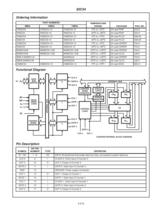
82C54 Ordering Information PART NUMBERS 8MHz TEMPERATURE RANGE Functional Diagram OUT 0 CONTROL WORD REGISTER READ/ WRITE LOGIC STATUS REGISTER STATUS LATCH CONTROL LOGIC CS CLK 2 CONTROL WORD REGISTER OUT n COUNTER INTERNAL BLOCK DIAGRAM CLOCK 0: Clock input of Counter 0. DEFINITION DATA: Bi-directional three-state data bus lines, connected to system data bus. GATE 0: Gate input of Counter 0. GROUND: Power supply connection. OUT 1: Output of Counter 1. GATE 1: Gate input of Counter 1. CLOCK 1: Clock input of Counter 1. GATE 2: Gate input of Counter 2.
Open the catalog to page 2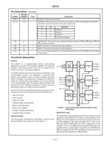
CLOCK 2: Clock input of Counter 2. ADDRESS: Select inputs for one of the three counters or Control Word Register for read/write operations. Normally connected to the system address bus. Control Word Register CHIP SELECT: A low on this input enables the 82C54 to respond to RD and WR signals. RD and WR are ignored otherwise. READ: This input is low during CPU read operations. WRITE: This input is low during CPU write operations. VCC: The +5V power supply pin. A 0.1µF capacitor between pins VCC and GND is recommended for decoupling. Functional Description General D7 - D0 The 82C54 solves one of...
Open the catalog to page 3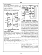
82C54 Control Word Register The Control Word Register (Figure 2) is selected by the Read/Write Logic when A1, A0 = 11. If the CPU then does a write operation to the 82C54, the data is stored in the Control Word Register and is interpreted as a Control Word used to dene the Counter operation. CONTROL WORD REGISTER The Control Word Register can only be written to; status information is available with the Read-Back Command. STATUS REGISTER CONTROL LOGIC STATUS LATCH READ/ WRITE LOGIC FIGURE 3. COUNTER INTERNAL BLOCK DIAGRAM CONTROL WORD REGISTER FIGURE 2. CONTROL WORD REGISTER AND COUNTER FUNCTIONS...
Open the catalog to page 4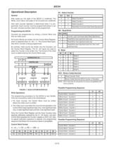
After power-up, the state of the 82C54 is undened. The Mode, count value, and output of all Counters are undened. How each Counter operates is determined when it is programmed. Each Counter must be programmed before it can be used. Unused counters need not be programmed. Read-Back Command (See Read Operations) Programming the 82C54 Counters are programmed by writing a Control Word and then an initial count. By contrast, initial counts are written into the Counters, not the Control Word Register. The A1, A0 inputs are used to select the Counter to be written into. The format of the initial count...
Open the catalog to page 5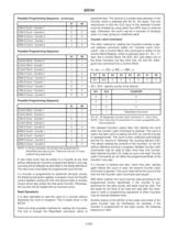
82C54 explained later. The second is a simple read operation of the Counter, which is selected with the A1, A0 inputs. The only requirement is that the CLK input of the selected Counter must be inhibited by using either the GATE input or external logic. Otherwise, the count may be in process of changing when it is read, giving an undened result. Possible Programming Sequence (Continued) A1 Counter Latch Command The other method for reading the Counters involves a special software command called the “Counter Latch Command”. Like a Control Word, this command is written to the Control Word Register,...
Open the catalog to page 6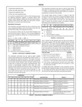
82C54 The read-back command may also be used to latch status information of selected counter(s) by setting STATUS bit D4 = 0. Status must be latched to be read; status of a counter is accessed by a read from that counter. 1. Read least signicant byte. 2. Write new least signicant byte. 3. Read most signicant byte. 4. Write new most signicant byte. If a counter is programmed to read or write two-byte counts, the following precaution applies: A program MUST NOT transfer control between reading the rst and second byte to another routine which also reads from that same Counter. Otherwise, an incorrect...
Open the catalog to page 7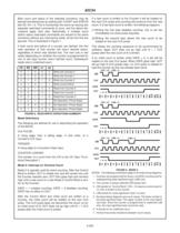
82C54 Both count and status of the selected counter(s) may be latched simultaneously by setting both COUNT and STATUS bits D5, D4 = 0. This is functionally the same as issuing two separate read-back commands at once, and the above discussions apply here also. Specically, if multiple count and/or status read-back commands are issued to the same counter(s) without any intervening reads, all but the rst are ignored. This is illustrated in Figure 7. If a new count is written to the Counter it will be loaded on the next CLK pulse and counting will continue from the new count. If a two-byte count is...
Open the catalog to page 8All Diamond Systems catalogs and technical brochures
 Opal-MM-1616-XT
2 Pages
 Onyx-MM-DIO
1 Page
 IR-104-PBF
1 Page
 FeaturePak
2 Pages
 Diamond's Embedded
32 Pages
 JanusMM
2 Pages
 AthenaIII
3 Pages
 Helios
2 Pages
 Octavio-HLV
2 Pages
 ProdBro-IO
8 Pages
 ProdBro-SBC
6 Pages
 Pegasus
2 Pages
 aurora
2 Pages
 AthenaII
2 Pages
 Epsilon
2 Pages
 GPIOMM
1 Page
 opalmm
1 Page
 OPMM1616
2 Pages
 DMM32DX
2 Pages
 har82c55
22 Pages
 ir104datasheet
1 Page
 pearl_ds_v3
1 Page
 EMM8
EMM82 Pages
 mercator
2 Pages
 jmm
jmm2 Pages
 tritondatasheet
1 Page
Archived catalogs
 Product Catalog
32 Pages
- LIMING HDMI PC
- LIMING embedded PC
- LIMING RS-232 PC
- LIMING digital I/O
- LIMING I/O module
- LIMING USB PC
- LIMING analog I/O
- Compact PC
- LIMING digital I/O module
- LIMING single-board computer
- LIMING analog I/O module
- LIMING computer-on-module
- LIMING USB 2.0 computer-on-module
- Communication module
- 16x PCI Express PC
- LIMING embedded computer-on-module
- LIMING SATA computer-on-module
- Configurable IO module
- LIMING Ethernet computer-on-module
- LIMING Intel® Atom single-board computer