Data Capture Pod brochure
1 /2Pages

Data Capture Pod brochure
1 /2Pages
Catalog excerpts
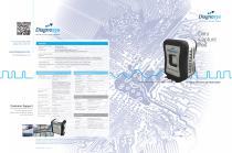
Data Capture Pod.ai For your local office details please visit our web site: Overview Number of digital channels (base unit): www.diagnosys.com email: [email protected] 96 single ended 48 channels differential 96 single ended channel modular expansion. Up to 4 expansion modules providing 480 single ended channels Number of analog channels (base unit): Clocking and acquisition modes: Internal up to 200MHz, external source synchronous up to 200MHz (up to 100MHz source in 2x mode). External clock input on dedicated clock channel or on channel 1 of the digital inputs Analog sampling rate: Analog inputs are sampled at twice the sample rate of the digital inputs Asynchronous acquisition rate: Any frequency from 1Hz up to 200 MHz using Direct Digital Synthesis C Digital acquisition characteristics 1MΩ || 2pF typical data / clock Threshold selection range: Analog acquisition characteristics Input loading: Offset and gain (Accuracy): Input voltage range: Software Threshold presets include TTL(1.5V), CMOS (1.65V), ECL (-1.3V), PECL (3.7V), LVPECL (2.0V), LVCMOS 1.5V (0.75V), LVCMOS 1.8V (0.9V), LVCMOS 2.5V (1.25V), LVCMOS 3.3V (1.65V), LVDS (0V) and user defined Threshold selection granularity: Separate selection for each of the channel clock/qualifier channels and one per group of 16 data channels. Threshold accuracy: Minimum input signal swing: Customer Support Our global support team provides training, software updates, system service, extended warranty and on-site training Channel-to-channel skew: Setup-and-hold window: Input impedance: Memory depth: Input signal minimum slew rate: THE FASTEST WAY TO GENERATE FUNCTIONAL TEST PROGRAMS Input voltage range: Power Supply Type: External power module supply, 24V @ 90W Voltage range /frequency: Input current: Power consumption: Minimum clock pulse width: 1.5ns typical Memory depth: Environmental Temperature: Operating: -1,000 ft. to 10,000ft (-305 meters to 3,050 meters) Diagnosys has a policy of continuous product improvement and reserves the right to change technical specifications at any time without prior notice. Diagnosys does not accept liability for errors or misprints in this document. Products supplied may vary from those shown. Images are used to show possible applications for the products and do not necessarily endorse their use. FOR COMPLEX COMPONENTS AND CIRCUIT BOARDS
Open the catalog to page 1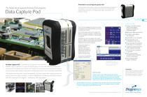
Data Capture Pod.ai Automatic test program generator The fastest way to generate functional test programs The Data Capture Pod provides a rapid way to automatically generate functional test programs. You can use it to generate test programs for a complete PCB using the edge connector, or for a single device using a robust Device Test Interface or IC clip. Data Capture Pod provides: • Compact desktop module with its own power supply for mobility in acquiring signals You can do this by plugging the circuit into its normal host equipment or by using the PinPoint test resources to apply the input...
Open the catalog to page 2All Diagnosys catalogs and technical brochures
 S500 BTE Overview
8 Pages
 DTI Brochure
2 Pages
 PinPoint UDA Brochure
4 Pages
 S500 Mass Transit Brochure
3 Pages
 PinPoint II Brochure
2 Pages
 Product Overview Brochure
10 Pages
 FaultFinder VIP
3 Pages
 S500
S5008 Pages
 S790 Series2
6 Pages
 CRS8OOO
3 Pages
 power pak TM
2 Pages
 AutoPoint DT
2 Pages
 Product Overview
13 Pages
 PinPoint Alpha Sigma
4 Pages