- Catalogs
- DI NICOLA INFINAM
- Sleeve valves


- Products
- Catalogs
- News & Trends
- Exhibitions
Sleeve valves
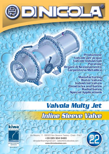
Sleeve valves
The document discusses the VH4 Type multijet sleeve valve, designed to dissipate kinetic energy in pipelines, thereby preventing negative phenomena such as cavitation, vibration, and noise. Cavitation, in particular, is highlighted as a significant issue due to its potential to cause stress and damage through the implosion of gas bubbles near metallic parts.
Specifications
The VH4 valve is constructed robustly to minimize vibration during operation. It dissipates energy internally, converting static energy into kinetic energy by altering flow directions. This design ensures that even if cavitation occurs, it does not damage the valve or pipeline.
Valve Dimensions and Flow Rates
The document provides a table of valve dimensions and corresponding maximum flow rates for various diameters (DN) and pressure ratings (PN). For example, a DN 200 valve with a PN of 6-40 has a maximum flow rate of 0.0 - 0.3 m³/s, while a DN 2000 valve with a PN of 6-16 has a maximum flow rate of 2.0 - 14 m³/s.
Flow Rate Diagrams
The flow rate diagram varies based on the valve's intended use. For regulating valves, the flow rate changes linearly with minimal head loss. For dissipation purposes, smaller hole diameters with variable pitch are used, resulting in higher head loss.
Head Loss Coefficient
The document includes a graph showing the head loss coefficient (K) against the valve opening percentage, indicating how head loss varies with valve opening from 10% to 100%.
Catalog excerpts
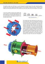
INLINE SLEEVE VALVES The pipeline multijet valve VH4 Type it is used to dissipate the cinetic Energy of the water inside the pipeline, avoiding ≤the common negative phenomena present on it as: Cavitation, vibration and noises. Ponted the most negative and important phenomenon is the cavitation one that causes high stress and damages on the pipeline. In fact the cavitation produces gas bubbles that quickly implode. In case that these bubbles formed near metallic parts it would produce damages, erosion and vibration on the those as shown in the schematic figure beside. High risk damage zone The...
Open the catalog to page 2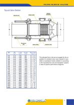
INLINE SLEEVE VALVES Tipycal Valve Section The indicated flow is the one we suggest for the regulation of a standard valve. Upon request it is possible to manufacture holes cylinders in according to the requested flow rate and dissipation capacity in base to specific performance diagrams.
Open the catalog to page 3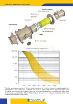
INLINE SLEEVE VALVES K (head loss coefficient) - opening (%) 1.000.000 The Flow rate diagram depends on the type of the required use for the valve. In case of a regulating valve use, the diagram will have a lower value variation of flow against the opening degree in the range of operating work, in order to have a more linear variation of flow rate with a minimum head loss. In case the valve use is firstly for dissipation use, the diameter of holes of the cylinder will be made smaller with variable pitch and so with more head loss than the other config
Open the catalog to page 4All DI NICOLA INFINAM catalogs and technical brochures
 Static mixers
11 Pages
 Aerating valve
3 Pages
 Introduction to Di Nicola
12 Pages
 Cast steel gate valves
8 Pages
 Globe valves
6 Pages
 Ball valves
12 Pages
 Clasar check valves
8 Pages
 Penstocks
16 Pages
 Eccentric ball valves
8 Pages
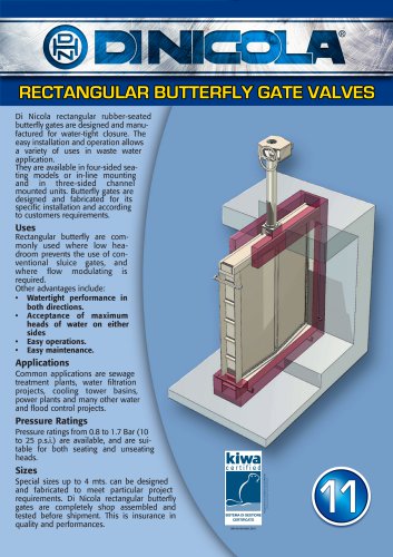 Rectangular butterfly valves
4 Pages
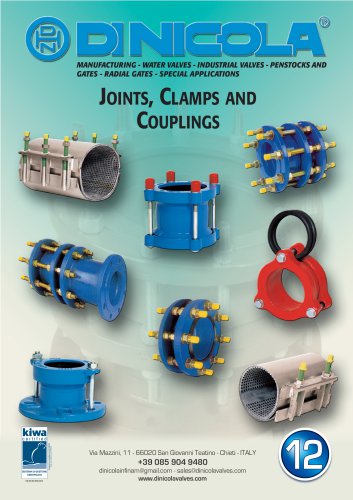 Joints and repair clamps
8 Pages
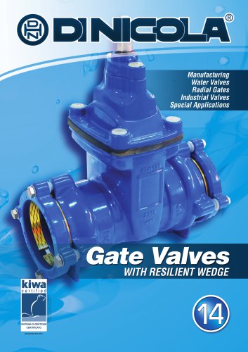 Resilient wedge gate valves
8 Pages
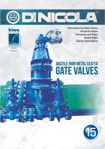 Metal seated gate valves
16 Pages
 Chain screens
4 Pages
 Wafer and lug butterfly valves
12 Pages
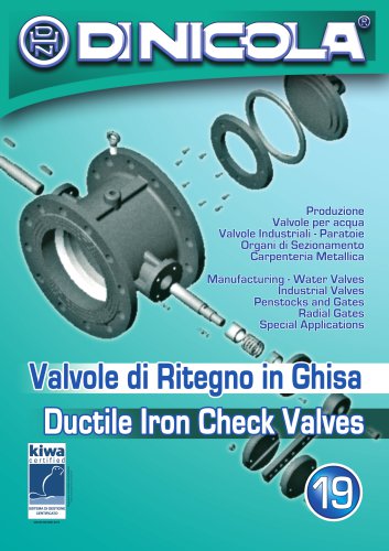 Non return check valves
12 Pages
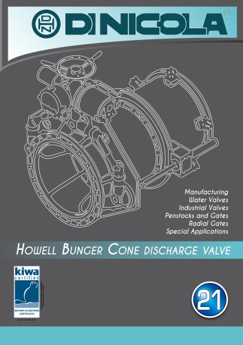 Howell Bunger valve
8 Pages
 Insulating monolithic joint
4 Pages
 Needle - plunger valve
7 Pages