
Catalog excerpts

NO. 6 & NO. 8 POWER BENDER INSTRUCTION MANUAL DiAcro METAL FABRICATION EQUIPMENT Toll Free: (855) 651-8948 - www.diacro.com - Fax: (651) 342-1293 12430 55th St. No. - Oak Park Heights, MN 55082 - USA
Open the catalog to page 1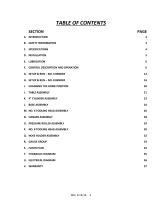
M. NO. 6 TOOLING HEAD ASSEMBLY 26 P. NO. 8 TOOLING HEAD ASSEMBLY 30
Open the catalog to page 2
A. Introduction This instruction manual serves two purposes: 1. It outlines essential information for installation, operation, and maintenance of the PLC controlled No. 6 and No. 8 Power Bender. 2. It gives a complete parts breakdown identified by number, should replacements be required. It is recommended that the operator become familiar with the bender's instructions and operating details. It is also recommended that the foreman or supervisor familiarize himself with the operating details of the machine to insure its continued efficient service. The Di-Acro Power Benders are designed to...
Open the catalog to page 3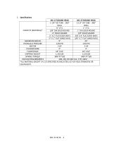
C. Specifications NO. 6 TOOLING HEAD NO. 8 TOOLING HEAD 1-1/4” OD TUBE - .060” 1-1/2” OD TUBE - .060” WALL WALL ¾” I.P.S. 1” I.P.S. CAPACITY (MATERIAL)* 5/8” DIA SOLID ROUND 1” DIA SOLID ROUND ½” SOLID SQUARE 7/8” SOLID SQUARE ¼” X 2” FLAT (EASY WAY) 3/8” X 4” FLAT (EASY WAY) ¼” X 1” FLAT (HARD WAY) 3/8” X 1” FLAT (HARD WAY) MAXIMUM RADIUS 9” 24” HYDRAULIC PRESSURE 1250 PSI 1250 PSI MOTOR 3 HP 3 HP CYLINDER BORE 4” 4” FLOOR SPACE 18” X 62” 18” X 62” SHIPPING WEIGHT 1,150 LBS 1,150 LBS SPINDLE TORQUE 3487 FT*LBS 3487 FT*LBS VOLTAGE REQUIREMENTS 208, 230, OR 460 VAC, 3 PH, 60HZ *ALL MATERIAL...
Open the catalog to page 4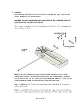
D. Installation During shipment, the bender may have accumulated a coating of dust or grit. Remove all dirt and rust preventative with cleaning solvent. WARNING: To prevent serious bodily injury fasten machine to floor through four holes (5/8” diameter) provided in the base of the machine. When shipped, the gauge is removed for packing purposes. Install one of the two gauge groups as shown below if desired. Note: The Stop Rod Weldment is inserted through the table assembly from the Operator’s Console side of the table. The appropriate Gauge Group is then installed onto this weldment from...
Open the catalog to page 5
stop arms are not located as above, the group will be out of balance and may cause binding of the knurled knob. Connect electricity to a three-phase input supply making certain that the transformer and motor are connected properly for power being supplied. (208-230, or 460 VAC). Check pump rotation. Power up the machine. Start the hydraulics by rotating the emergency stop button clockwise, pressing the power on/reset button, and pressing the green start button on the operator console. Open the door in the base and make sure that the pressure gauge indicates a value around 1250 psi. If no...
Open the catalog to page 6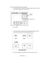
2. HMI Screen Displays (Without Recipe Operation) The HMI panel layout is shown in the photo below. Make note of the Function Keys, Numeric Keypad, and Enter/Return key. Two screen options are provided with the standard power bender HMI. The Main Screen as shown below is used during production runs. This screen displays the Bend Setpoint, Bend Value, and Parts Counter.
Open the catalog to page 7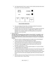
The “Manual/Homing” Screen is used to run the machine manually and to home the machine. This screen is shown below. This screen displays the Bend Value, and indicates whether the machine is Homing or Homed during the Homing procedure. On either screen, the Function Keys are used to perform whatever functions are displayed on the screen at the time, or toggle between different modes as displayed. This is covered in detail in the Homing, Manual, and Automatic Operation sections that follow. 3. Manual Operation CAUTION: When operating the power bender in manual mode, it is possible to crash...
Open the catalog to page 8
• Once the desired bend has been set up, place your fingers in the two-hand safety switches located on either side of the Operator's Console. Note that the machine will begin moving when your fingers enter these switches. It will not stop until your fingers are removed or the machine runs out of travel. • When the desired travel has been reached, take your fingers off the safety switches. Press F2 to reverse the travel if desired. Actuate the safety switches to move the bender back to the point you started. 4. Homing the Bender • When the machine is initially powered up, the Main Screen...
Open the catalog to page 9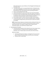
Manual/Homing Screen, press F4 (Return). This will toggle the HMI display back to the Main Screen. In the Main Screen, press F1 to enter the Bend Set Point. The Bend Set Point value should be highlighted on the HMI. Use the numeric keypad to enter the desired Bend Set Point. Save the Bend Set Point by pressing Enter/Return. Press F1 to exit the Bend Set Point mode. If desired, the production counter can be reset in this screen by pressing F2. Activate the bender by actuating the two-hand safety switches on the sides of the operator console. The bender will then extend until the safety...
Open the catalog to page 10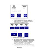
For Automatic operation with the recipe option, a recipe must be programmed and selected. Press F1 to advance to the recipe screen. The Recipe Setup Screen Display is shown below. When this screen is displayed, recipes can be programmed and selected. Press F1 to bring up the recipe selection popup. Use the numeric keypad to enter the desired recipe (1 to 75 are available for use), and press Enter/Return to close the popup. The recipe number should be displayed in the box under Recipe Number on the display. To Program bends, press the function key (F5-F8) for the corresponding bend value to...
Open the catalog to page 11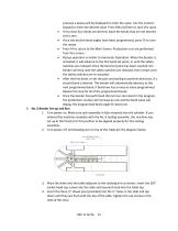
pressed, a popup will be displayed to enter the value. Use the numeric keypad to enter the desired value. Press Return/Enter to save this value. If less than four bends are desired, leave the bends that are not desired set to zero. Once the desired bend angles have been programmed, press F3 to save the recipe. Press F4 to return to the Main Screen. Production runs are performed from this screen. Recipe operation is similar to Automatic Operation. When the bender is activated, it will advance to the first bend set point, or until the safety switches are released. Once the bend set...
Open the catalog to page 12All Di-Acro catalogs and technical brochures
-
 MODEL 12 HAND SHEAR
13 Pages
-
 HERCULES HYDRAULIC
27 Pages
-
 Model 2 Punch Press
12 Pages
-
 Model 24 Slip Roller
11 Pages
-
 Model 12 Slip Roller
11 Pages
-
 Model 24 Shear
13 Pages
-
 Model 12 Shear
13 Pages
-
 Model 2 Rod Parter
9 Pages
-
 Model 2 Tab Notcher
12 Pages
-
 Model 36 Finger Brake
10 Pages
-
 Model 24 Finger Brake
9 Pages
-
 Model 4 Bender
12 Pages
-
 Model 3 Bender
11 Pages
-
 Model 1A Bender
8 Pages
-
 Model 2 Bender
11 Pages
-
 Model 1 Bender
9 Pages
-
 Products Catalog
20 Pages