
Catalog excerpts

di-ocro® Metal Fabrication Equipment Toll Free: (855)651-8948 * www.diacro.com • Fax:(651)342-1293 12430 55th St No • Oak Park Heights, MN 55082 • USA
Open the catalog to page 1
L. NO. 6 TOOLING HEAD ASSEMBLY N. PRESSURE ROLLER ASSEMBLY O. NO. 8 TOOLING HEAD ASSEMBLY P. NOSE HOLDER ASSEMBLY
Open the catalog to page 2
A. Introduction This instruction manual serves two purposes: 1. It outlines essential information for installation, operation and maintenance of the No. 6 and No. 8 Power Bender. 2. It gives a complete parts breakdown identified by number, should replacements be required. It is recommended that the operator become familiar with the bender’s instructions and operating details. It is also recommended that the foreman or supervisor familiarize himself with the operating details of the machine to insure its continued efficient service. The Di-Acro Power Benders are designed to accommodate two...
Open the catalog to page 3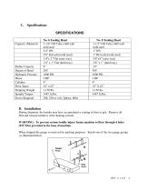
D. Installation During shipment, the bender may have accumulated a coating of dust or grit. Remove all Dirt and rust preventative with cleaning solvent. WARNING: To prevent serious bodily injury fasten machine to floor through 4 holes (5/8” Dia) provided in the base of machine. When shipped the gauge is removed for packing purposes. Install one of the two gauge groups as illustrated below.
Open the catalog to page 4
NOTE: Install gauge group “A” for short or single length bends. Install group “B” for longer or multiple length bends. NOTE: It is suggested that all four stop arms be placed at right angles to each other even if only one or two are needed so that the knurled knob can be easily turned in to position the stops. Connect electricity to a thee phase input power supply making certain the transformer and motor are connected properly for power being supplied (208, 230, or 460). Check pump rotation. Proper rotation is shown by the directional arrow on shroud located at the top of the motor. To...
Open the catalog to page 5
• The “F1” button (when in the “Production” screen is used to enter the “Bend Value” screen “F1” (ESC) or <RET> is used to return back to the “Production screen. 3. Manual Operation • Start Hydraulic pump with the “START” button. • Go to the “Manual/Homing” screen; press “F4” if in the “Production” screen. • Toggle “F2” button between “Extend” & “Retract” to control the rotation direction of the tooling head. • Position and hold fingers in the two hand safety switch to activate rotation. Rotation will stop when fingers are removed from the safety switch or the hydraulic cylinder has reached...
Open the catalog to page 6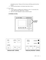
to the Home position. Rotation will not stop once the Home position has been reached. If the desired bend angle is not obtained repeat Step 4 (above) Cycle Counter • A cycle counter is available in the “Production” screen. It is activated in the “Auto” mode when the “Bend Value” is reached. • Press “F3” in the “Production” screen to reset the counter.
Open the catalog to page 7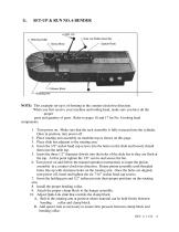
Bending Collar Quik Lok Roller Assembly Spacer Rods Clamp Block Follower Block NOTE: This example set-up is of forming in the counter-clockwise direction. When you first receive your machine and tooling head, make sure you have all the proper parts and quantity of parts. Refer to pages 16 and 17 for No. 6 tooling head components. 1. Turn power on. Make sure that the rack assembly is fully retracted into the cylinder. Once in position, turn power off. 2. Place rotating arm assembly on machine top as shown on this page. 3. Place slide bar adjacent to the rotating arm. 4. Insert the 3/8”...
Open the catalog to page 8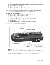
11. Adjust Quik-Lok slide that controls follow block (excessive pressure not necessary). 12. Clamp material with clamp block. 13. Clamp material with follow block. 14. Follow Manual Operations Instructions to test bend a part. NOTE: After desired part has been achieved, material stop indexes can be adjusted and follow automatic operation instruction to set up for production. To Set Up For Clockwise Bending 1. Remove Quik-Lok that controls clamp block from rotating arm. 2. Remove Quik-Lok that controls follow block. 3. Remove rotating arm and slide. 4. Remove and flip over screw support on...
Open the catalog to page 9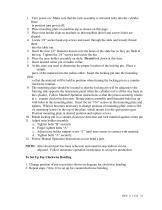
1. Turn power on. Make sure that the rack assembly is retracted fully into the cylinder. Once in position turn power off. 2. Place mounting plate on machine top as shown on this page. 3. Place nose holder slide on machine so that machine dowel and screws holes are aligned. 4. Locate 3/8” socket head cap screws and insert through the slide and loosely thread them into the table top. 5. Insert the four 1/2” diameter dowels into the holes of the slide bar so they are flush at the top. Tighten the 3/8” screws and secure the bar. 6. Place the nose holder assembly on slide. Do not bolt down at...
Open the catalog to page 10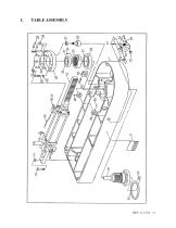
TABLE ASSEMBLY
Open the catalog to page 11
POWER BENDER TABLE ASSEMBLY PARTS LIST 8700000-060 ITEM PART NUMBER DESCRIPTION QTY
Open the catalog to page 12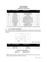
POWER BENDER TABLE ASSEMBLY PARTS LIST “CONTINUED” ITEM PART NUMBER DESCRIPTION QTY SEAL KITS (NOT SHOWN) 8150730-116 PISTON SEAL KIT NOTE: When replacing old style Rack (P/N 8150121-607), drill 3/8 dia. hole in rack and align with hole in piston rod. Install 3/8” dowel pin.
Open the catalog to page 13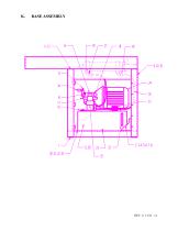
BASE ASSEMBLY
Open the catalog to page 14
POWER BENDER BASE ASSEMBLY PARTS LIST 121871-000 ITEM PART NUMBER DESCRIPTION QTY
Open the catalog to page 15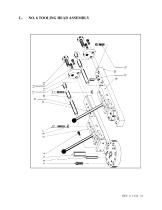
NO. 6 TOOLING HEAD ASSEMBLY
Open the catalog to page 16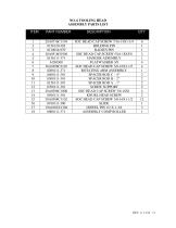
NO. 6 TOOLING HEAD ASSEMBLY PARTS LIST ITEM PART NUMBER DESCRIPTION QTY
Open the catalog to page 17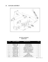
HANGER ASSEMBLY PARTS LIST ITEM PART NUMBER DESCRIPTION QTY
Open the catalog to page 18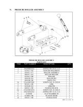
PRESSURE ROLLER ASSEMBLY PARTS LIST ITEM PART NUMBER DESCRIPTION QTY
Open the catalog to page 19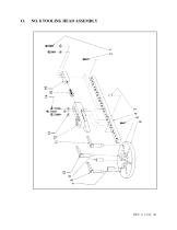
NO. 8 TOOLING HEAD ASSEMBLY
Open the catalog to page 20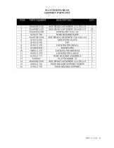
NO. 8 TOOLING HEAD ASSEMBLY PARTS LIST ITEM PART NUMBER DESCRIPTION QTY
Open the catalog to page 21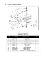
NO. 8 TOOLING HEAD ASSEMBLY PARTS LIST ITEM PART NUMBER DESCRIPTION QTY
Open the catalog to page 22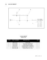
GAUGE GROUP PARTS LIST ITEM PART NUMBER DESCRIPTION QTY
Open the catalog to page 23
THIS PAGE INTENTIONALLY LEFT BLANK Reference separate diagrams included in envelope
Open the catalog to page 26All Di-Acro catalogs and technical brochures
-
MODEL 12 HAND SHEAR
13 Pages
-
Model 2 Punch Press
12 Pages
-
Model 24 Slip Roller
11 Pages
-
Model 12 Slip Roller
11 Pages
-
Model 24 Shear
13 Pages
-
Model 12 Shear
13 Pages
-
Model 2 Rod Parter
9 Pages
-
Model 2 Tab Notcher
12 Pages
-
Model 36 Finger Brake
10 Pages
-
Model 24 Finger Brake
9 Pages
-
Model 6 - 8 Bender
37 Pages
-
Model 4 Bender
12 Pages
-
Model 3 Bender
11 Pages
-
Model 1A Bender
8 Pages
-
Model 2 Bender
11 Pages
-
Model 1 Bender
9 Pages
-
Products Catalog
20 Pages


