DSE704-4120
1 /2Pages

DSE704-4120
1 /2Pages
Catalog excerpts
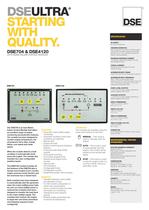
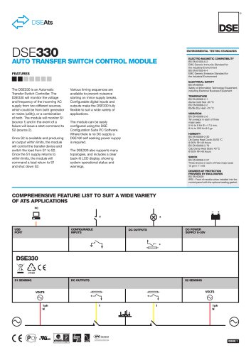
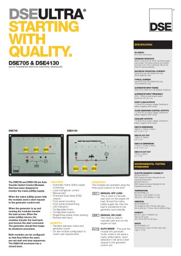
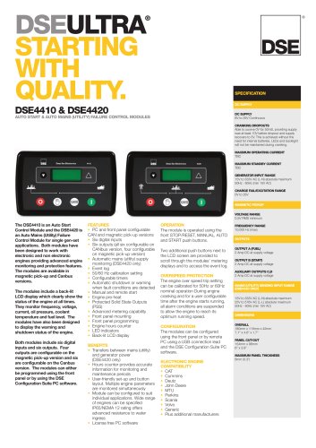
® DSEULTRA® STARTING WITH QUALITY. SPECIFICATION ENVIRONMENTAL TESTING STANDARDS The DSE704 is an AutoMains Failure ControlModule that offers an excellent range of engine monitoring and protection features. Themodule has been designed to monitor engine temperature, low oil pressure, fail to start, charge failure, over speed and under speed. When themodule detects a fault condition it automatically shuts down the engine. The module also includes two user configurable auxiliary inputs. The DSE4120module includes all the features of the DSE704 plus a tamper proof engine hours counter, engine exercise mode function and the enclosure has a closed back. Bothmodules have been designed to automatically start the generator when the mains (utility) power fails. As soon as mains (utility) power is restored the modules have been designed to transfer the load back to the mains (utility) supply. The modules then instruct the engine to begin the cool down procedure and stopping sequence (user configured). FEATURES • Automatic mains (utility) supply monitoring • Automatic shutdown when fault conditions are detected • Manual start • Engine pre-heat • Engine monitoring and protection features • Protected Solid State (PSS) outputs • Front panel mounting • Front panel programming • Tamper proof engine hours counter • Remote start • LED indicators • Configurable timers • Configurable outputs • Single/three phase mains sensing BENEFITS • Transfers between mains (utility) and generator power • On-site module configuration to match user requirements • Hours counter provides accurate information for monitoring maintenance and warranty periods • Multiple engine parameters are monitored simultaneously OPERATION The modules are operated using the three push buttons on the front: MANUAL – This mode is used to manually start the engine. AUTO – This mode is used to automatically start the engine. The module will be started by the remote start signal. STOP – This button is used to stop the engine when it is running in either manual or automatic mode. ELECTROMAGNETIC CAPABILITY BS EN 61000-6-2 EMC Generic Emission Standard for the Industrial Environment BS EN 61000-6-4 EMC Generic Emission Standard for the Industrial Environment TEMPERATURE BS EN 60068-2-2 Test Ab to +70oC 60067-2-2 Hot Test Ab to -30oC 60068-2-1 Cold VIBRATION BS EN 60068-2-6 Ten sweeps in each of three major axes 5Hz to 8Hz @ +/-7.5mm, 8Hz to 500Hz @ 2gn HUMIDITY BS 2011 part 2.1 60068-2-30 Test Cb Ob Cyclic 93% RH @ 40oC for 48 hours SHOCK BS EN 60068-2-27 Three shocks in each of three major axes 15gn in 11mS DC SUPPLY 8V to 35V continuous CRANKING DROPOUTS Able to survive 0V for 50mS, providing supply was at least 10V before dropout and supply recovers to 5V. This is achieved without the need for internal batteries. MAXIMUMOPERATING CURRENT 170mA(12V), 280mA(24V) (DSE4120 only) 50mA (DSE704 only) TYPICAL CURRENT 35mA(12V and 24V) (DSE 4120 only) 12mA (704 only) ALTERNATOR INPUT RANGE 75V(L-N) to 333V AC (L-N) absolute maximum ALTERNATOR INPUT FREQUENCY 50Hz – 60Hz at rated engine speed (minimum:75V AC L-N) (Crank disconnect from 15V L-N @ 20Hz) Overspeed +14% (+24% overshoot) Underspeed -20% START & FUEL OUTPUTS 1.2 Amp DC at supply voltage. Switches to battery negative when active AUXILIARY OUTPUTS 1.2 Amp DC at supply voltage. Switches to battery negative when active DSE704 DIMENSIONS 165mm x 125mm x 29mm 6.5” x 4.9” x 1.2” DSE704 CUT OUT 149mm X 109mm 5.9” x 4.3” DSE4120 DIMENSIONS 171mm x 115mm x 49mm 6.7” x 4.5” x 1.9” DSE4120 PANEL CUT OUT 154mm x 98mm 6.1” x 3.9” CHARGE FAIL 8 Volt Charge Fail at 12 Volts, 16 Volt Charge Fail at 24 Volts DSE704 & DSE4120 AUTOMAINS FAILURE CONTROLMODULES DSE704 DSE4120
Open the catalog to page 1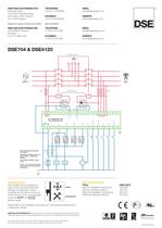
® DSE704 & DSE4120 CONFIGURATION The modules can be configured to match user’s individual parameter settings. Configuration mode is accessed via the switch at the rear of the module. Once in configuration mode the AUTO-LED flashes rapidly. Please refer to the installation instructions for the parameter settings and configuration details. RELATEDMATERIALS TITLE PART NO’S DSE704 Installation Instructions 053-036 DSE704 Operators Manual 057-043 DSE4120 Installation Instructions 053-021 DSE4120 Operators Manual 057-023 DEEP SEA ELECTRONICS INC 3230 Williams Avenue Rockford IL 61101-2668 USA TELEPHONE...
Open the catalog to page 2All DES catalogs and technical brochures
 dseL401 MKII
2 Pages
 DSE9462
2 Pages
 DSE9473 & DSE9483
2 Pages
 DSE9480 MKII
2 Pages
 dse9474 & dse9484
2 Pages
 DSE4510 MKII
2 Pages
 DSE4610
2 Pages
 DSE6110 MKII
2 Pages
 DSE7110 MKII
2 Pages
 dse7310/20 MKII
2 Pages
 dse9120-9240
2 Pages
 dse9470947294809481
2 Pages
 dse860-65
1 Page
 dse330
2 Pages
 dse9480
2 Pages
 edv-030-1250-024
2 Pages
 edv-015-1250
2 Pages
 dse705-4130
2 Pages
 dse330-
2 Pages
 dse8700
2 Pages
 dse431020
2 Pages
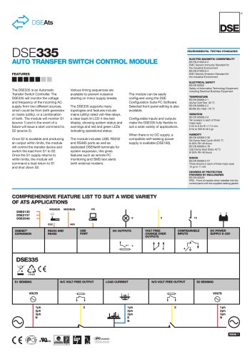 dse335
2 Pages
 dse3210-
2 Pages
 DSEEDS-033-1000-048-A
2 Pages
 500
5002 Pages
 1000
10002 Pages
 eda-033-0700-048
2 Pages
 DSE5310-5320
4 Pages
 DSE7210-20
4 Pages
 DSE7310-20
4 Pages
 DSE7110-20
4 Pages
 DSE705-4130
2 Pages
 DSE710-720
2 Pages
 DSE703-4110
2 Pages
 DSE4410-20
2 Pages
 DSE6110-20
2 Pages
 DSE511
2 Pages
 DSE512
2 Pages
 DSE402
2 Pages
 DSE501K
2 Pages
 DSE8700
2 Pages
 DSE701 & DSE702
2 Pages
 DSE703 & DSE4110
2 Pages
 DSE3110
2 Pages
 DSE6010 & DSE6020
2 Pages


Archived catalogs
 DSE5210-5220
4 Pages
- Power supply unit
- DC power supply
- Display module
- AC/DC power supply
- LCD display panel
- Challenge Power Transmission automation software
- Windows software
- Real-time software
- Control software
- Switching power supply
- Monitoring software solution
- Communication gateway
- Battery charger
- Ethernet gateway
- Programmable logic controller
- DIN rail power supply
- Serial gateway
- Programmable display system
- Lead battery charger
- Graphic display panel