DSE512

DSE512
- Micro-processor based design
- PC configuration capabilities
- Automatic shutdown on fault conditions
- Engine operational and alarm status indication
- LED alarm indication
- Configurable input and output functions
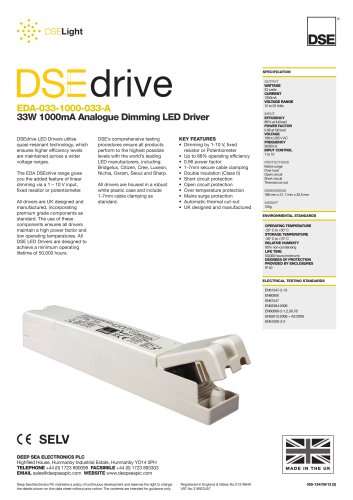
The Model 512 is a Manual Engine Control Module designed for OEMs to enhance engine control capabilities. It facilitates engine start and stop, indicates operational status, and manages fault conditions with automatic shutdown and LED indications. The module allows for customer alterations via PC using the 808 interface, providing real-time diagnostics. It features a two-position key switch for operation and a START pushbutton for engine cranking. Microprocessor control enhances manual start operations, including crank inhibit, automatic crank disconnect, and a crank limit timer.
Relay outputs are available for Fuel Solenoid, Start Output, and two configurable outputs, initially set for pre-heat and alarm functions. Configurable inputs include Low Oil Pressure, High Engine Temperature, and Remote Fuel On, with two auxiliary inputs for protection expansion. Multiple alarm channels monitor various conditions, with first alarms indicated by flashing LEDs and subsequent alarms by steady LEDs.
- DC Supply: 8V to 35V Continuous
- Cranking Dropouts: Survives 0V for 50ms
- Max Operating Current: 150mA at 12V, 180mA at 24V
- Max Standby Current: 15mA at 12V, 21mA at 24V
- Alternator Input Range: 15V - 300V AC RMS
- Alternator Input Frequency: 50Hz - 60Hz
- Magnetic Input Range: 0.5V to +/- 70V
- Magnetic Input Frequency: 10Hz to 10,000Hz
- Relay Outputs: 16 Amp DC for Start and Fuel, 5 Amp DC for Pre-heat/Auxiliary
- Dimensions: 96mm x 96mm x 140.5mm
- Operating Temperature Range: -15ºC to +55°C
The module is designed for front panel mounting with locking plug and socket connectors. A typical wiring diagram is provided for installation guidance.
Catalog excerpts
512 MANUAL START Issue 3 03/03/05 AP DEEP SEA ELECTRONICS FEATURES . Micro-processor based design . PC configuration . Automatic shutdown on fault condition . Provides engine operational status and alarm status . LED alarm indication . Configurable input and output functions DESCRIPTION The Model 512 is a Manual Engine Control Module which has been designed to allow the OEM to meet demand for increased capability within the industry. The module is used to start and stop the engine, indicating the operational status and fault conditions; automatically shutting down the engine and indicating the engine failure by means of a flashing LED. Any simultaneous faults are indicated by a steady LED. Selected operational sequences, timers and alarms can be altered by the customer. Alterations to the system are carried out using a PC and the 808 interface. This also provides the operator with real time diagnostic facilities to monitor the operation of the system. Operation of the module is via a two position key switch mounted on the front panel with STOP and RUN positions. A START pushbutton is fitted to facilitate engine cranking. Microprocessor control allows enhanced manual start operation, Crank inhibit if the engine is running, automatic crank disconnect and also a crank limit timer to prevent starter motor damage in the event of a fail to start occurring. DESCRIPTION (Continued) Relay outputs are provided for Fuel Solenoid Output, Start Output and two configurable outputs. The relays are factory configured as pre-heat and alarm output, however the relay function is configurable to activate on a range of functions, conditions or alarms. The relays supply positive plant supply out. Configurable inputs are available for Low Oil Pressure, High Engine Temperature and Remote Fuel On. This allows the module to function with N/O or N/C switches. Two fully configurable auxiliary inputs are provided to give protection expansion. These can be selected to be indication, warning or shutdown inputs either immediate or held off during start up. Uncommitted LEDS allow for annunciation. Multiple alarm channels are provided to monitor the following:- Overspeed, Charge Fail, Emergency Stop, Low oil pressure, High engine temperature, and programmable inputs as selected. First up alarm is indicated by a flashing LED. Subsequent alarms are displayed by a steady LED. The Remote Fuel On facility is intended for use where a dual engine start position is required. The module will turn on the fuel supply and provide all normal protections to the engine. However engine cranking must be performed externally to the module via a key switch or push-button connected in parallel with the module crank relay. The 500 series modules have been designed for front panel mounting. The module is fitted into the cut-out with the fixing clips removed. These are then fitted from the rear. Connection is via locking plug and socket connectors. SPECIFICATION DC Supply: 8V to 35 V Continuous. Cranking Dropouts: Able to survive 0 V for 50 mS, providing supply was at least 10 V before dropout and supply recovers to 5V. This is achieved without the need for internal batteries. Max. Operating Current: 150 mA at 12 V. 180 mA at 24 V. Max. Standby Current: 15 mA at 12 V. 21 mA at 24 V.(In stop position consumption is zero.) Alternator Input Range: 15V - 300 V ac RMS Alternator Input Frequency: 50Hz - 60 Hz at rated engine speed. Magnetic Input Range: 0.5 V to +/- 70 V (Clamped by transient suppressors) Magnetic Input Frequency:10Hz to 10,000 Hz at rated engine speed. Start Relay Output: 16 Amp DC at supply voltage. Fuel Relay Output: 16 Amp DC at supply voltage. Pre-heat/Auxiliary Relay Outputs: 5 Amp DC at supply voltage. Dimensions: 96mm x 96mm x 140.5mm (3.8” x 3.8” x 5.5”) Excluding Key-switch Charge Fail / Excitation Range: 0 V to 35 V Operating Temperature Range: -15ºC to +55°C
Open the catalog to page 1
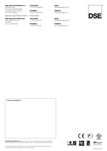
96.0mm96.0mm89.0mm133.0mm7.5mmPanel Cut-out: 90mmx90mm1131418 TYPICAL WIRING DIAGRAM Deep Sea Electronics Plc. Highfield House, Hunmanby Industrial Estate, North Yorkshire. YO14 0PH. ENGLAND Tel:+44 (0)1723 890099. Fax: +44 (0)1723 893303. Email: [email protected] Web: www.deepseaplc.com Deep Sea Electronics Inc. 3230 Williams Avenue Rockford, Illinois 61101-2668, U.S.A. Phone: +1 (815) 316-8706. Fax: +1 (815) 316-8708. Email: [email protected] Web: www.deepseausa.com CASE DIMENSIONS (3.8”) (5.2”) (3.5”) (3.8”) (0.3”) (3.54” x 3.54”) FFFNOTE:- When connected toa completed Panel/Gen-setReal...
Open the catalog to page 2All DES catalogs and technical brochures
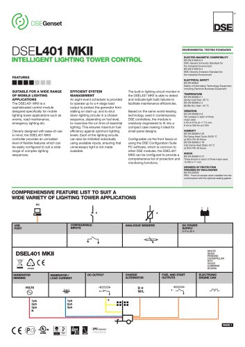 dseL401 MKII
2 Pages
 DSE9462
2 Pages
 DSE9473 & DSE9483
2 Pages
 DSE9480 MKII
2 Pages
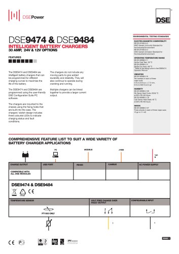 dse9474 & dse9484
2 Pages
 DSE4510 MKII
2 Pages
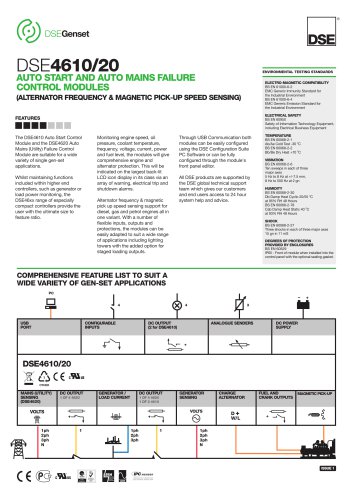 DSE4610
2 Pages
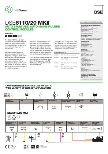 DSE6110 MKII
2 Pages
 DSE7110 MKII
2 Pages
 dse7310/20 MKII
2 Pages
 dse9120-9240
2 Pages
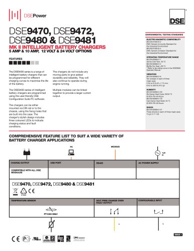 dse9470947294809481
2 Pages
 dse860-65
1 Page
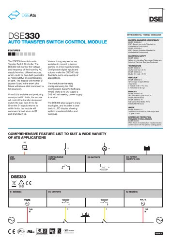 dse330
2 Pages
 dse9480
2 Pages
 edv-030-1250-024
2 Pages
 edv-015-1250
2 Pages
 dse705-4130
2 Pages
 dse330-
2 Pages
 dse8700
2 Pages
 dse431020
2 Pages
 dse335
2 Pages
 dse3210-
2 Pages
 DSEEDS-033-1000-048-A
2 Pages
 500
5002 Pages
 1000
10002 Pages
 eda-033-0700-048
2 Pages
 DSE5310-5320
4 Pages
 DSE7210-20
4 Pages
 DSE7310-20
4 Pages
 DSE7110-20
4 Pages
 DSE704-4120
2 Pages
 DSE705-4130
2 Pages
 DSE710-720
2 Pages
 DSE703-4110
2 Pages
 DSE4410-20
2 Pages
 DSE6110-20
2 Pages
 DSE511
2 Pages
 DSE402
2 Pages
 DSE501K
2 Pages
 DSE8700
2 Pages
 DSE701 & DSE702
2 Pages
 DSE703 & DSE4110
2 Pages
 DSE3110
2 Pages
 DSE6010 & DSE6020
2 Pages


Archived catalogs
 DSE5210-5220
4 Pages
- Power supply unit
- DC power supply
- Display module
- AC/DC power supply
- LCD display panel
- Automation software solution
- Windows software
- Real-time software
- Control software
- Switching power supply
- Monitoring software solution
- Communication gateway
- Battery charger
- Ethernet gateway
- DIN rail power supply
- Serial gateway
- Programmable display system
- Lead battery charger
- Graphic display panel