DSE402
1 /2Pages
DSE402
1 /2Pages
Catalog excerpts

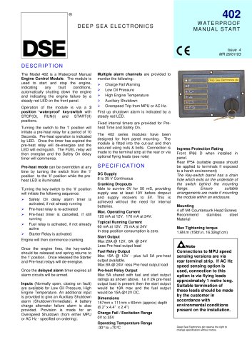
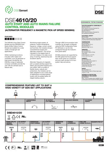
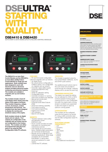
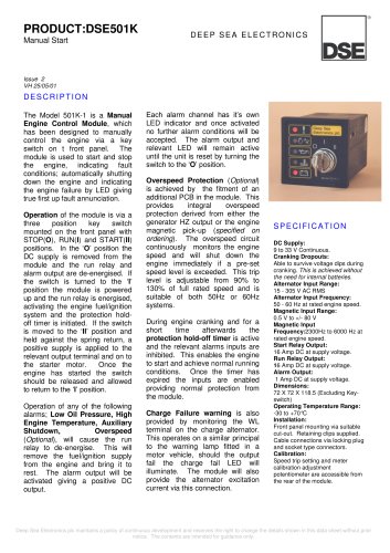
DEEP SEA ELECTRONICS 402 WATERPROOF MANUAL START The Model 402 is a Waterproof Manual Engine Control Module. The module is used to start and stop the engine, indicating any fault conditions, automatically shutting down the engine and indicating the engine failure by a steady red LED on the front panel. Operation of the module is via a 3 position ‘waterproof’ key-switch with STOP(O), RUN(I) and START(II) positions. Turning the switch to the ‘I’ position will initiate a pre-heat relay for a period of 10 Seconds. Pre-heat operation is indicated by LED. Once the timer has expired the pre-heat relay will de-energise and the LED will extinguish. The FUEL relay will then energise and the Safety On delay timer will commence. Pre-heat mode can be overridden at any time by turning the switch from the ‘I’ position to the ‘II’ position while the pre-heat LED is illuminated. Turning the key-switch to the ‘II’ position will initiate the following sequence: „« Safety On delay alarm timer is activated, if not already running „« Pre-heat relay is re-activated „« Pre-heat timer is cancelled, if still running „« Fuel relay is activated, if not already active „« Starter Relay is activated. Engine will then commence cranking. Once the engine fires, the key-switch should be released and spring returns to the ‘I’ position. Once released the Starter and Pre-heat relays will de-energise. Once the delayed alarm timer expires all alarm circuits will be armed. Inputs (Normally open, closing on fault) are available for Low Oil Pressure, High Engine Temperature. An additional input is provided to give an Auxiliary Shutdown alarm (Shutdown/Immediate). A battery charge alternator failure alarm is also provided. Provision is made for an Overspeed Shutdown (from either MPU or AC Hz - specified on ordering). Multiple alarm channels are provided to monitor the following: „« Charge Fail Warning „« Low Oil Pressure „« High Engine Temperature „« Auxiliary Shutdown „« Overspeed Trip from MPU or AC Hz. First up shutdown alarm is indicated by a steady red LED. Fixed internal timers are provided for Pre-heat Time and Safety On. The 402 series modules have been designed for front panel mounting. The module is fitted into the cut-out and then secured using nuts & bolts. Connection is made to the terminal strip at the rear or via optional flying leads (see note) SPECIFICATION DC Supply 8 to 35 V Continuous Cranking Dropouts Able to survive 0V for 50 mS, providing supply was at least 10V before dropout and supply recovers to 5V. This is achieved without the need for internal batteries. Max. Operating Current 120 mA at 12V. 170 mA at 24V. Typical Running Current 60 mA at 12V. 75 mA at 24V In stop position consumption is zero. Start Output Max 20A @ 12V, 8A @ 24V Less Pre-heat output load Fuel Relay Output Max 15A @ 12V - plus full 5A pre-heat output available. Max 8A @ 24V -less Pre-heat output load Pre-heat Relay Output Max 5A shared with fuel and start output ratings as shown above. I.e if 2A pre-heat output load is present then the start output would be 18A max and the fuel output would be 15A @12V DC. Dimensions 157mm x 111mm x 60mm (approx) depth (6.2” x 4.4” x 2.4”) Charge Fail / Excitation Range 0V to 35V Operating Temperature Range -30° to +70°C DESCRIPTION Ingress Protection Rating Front IP66 D when installed in panel. Rear IP54 (suitable grease should be applied to terminals if exposed to a harsh environment) The Key-switch barrel has a drain hole which exits on the underside of the switch behind the mounting flange. Ensure suitable arrangements are made if mounting the module within an enclosure. Mounting 4 off M4 Countersunk Head Screws Recommend stainless steel Material Max Tightening torque 1.6N.m (15lbf.in, 16.32kgf.cm) Issue 4 MR 29/01/03 Note Connections to MPU speed sensing versions are via rear terminal strip. If AC Hz speed sensing option is used, connection to this option is via flying leads approximately 1 metre long. Suitable termination of these leads should be made by the customer in accordance with environmental conditions present on the installation. Deep Sea Electronics plc reserve the right to change specification without notice.
Open the catalog to page 1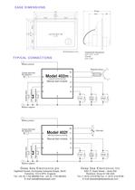
50.550.591.7510111173.573.5137.514715749.5All Dimensions in mmCUT OUT 92 X 138+1/-098 app.28 CASE DIMENSIONS Batttery positiveBatttery negative1011234+-9FuelheatPre-StartMagnetic pickup876Charge alternatorW/L terminalModel 402mManual start module15(magnetic pickup sensing)Batttery positiveBatttery negative10112349FuelheatPre-StartAlternator876Charge alternatorW/L terminalModel 402fManual start module15(Alternator frequency sensing)L1N TYPICAL CONNECTIONS Deep Sea Electronics Inc 5301 E. State Street – Suite 202 Rockford, Ilinois 61108 USA Tel +1 (815) 316-8706 Fax +1 (815) 316-8708 E-mail [email protected]...
Open the catalog to page 2All DES catalogs and technical brochures
 dseL401 MKII
2 Pages
 DSE9462
2 Pages
 DSE9473 & DSE9483
2 Pages
 DSE9480 MKII
2 Pages
 dse9474 & dse9484
2 Pages
 DSE4510 MKII
2 Pages
 DSE4610
2 Pages
 DSE6110 MKII
2 Pages
 DSE7110 MKII
2 Pages
 dse7310/20 MKII
2 Pages
 dse9120-9240
2 Pages
 dse9470947294809481
2 Pages
 dse860-65
1 Page
 dse330
2 Pages
 dse9480
2 Pages
 edv-030-1250-024
2 Pages
 edv-015-1250
2 Pages
 dse705-4130
2 Pages
 dse330-
2 Pages
 dse8700
2 Pages
 dse431020
2 Pages
 dse335
2 Pages
 dse3210-
2 Pages
 DSEEDS-033-1000-048-A
2 Pages
 500
5002 Pages
 1000
10002 Pages
 eda-033-0700-048
2 Pages
 DSE5310-5320
4 Pages
 DSE7210-20
4 Pages
 DSE7310-20
4 Pages
 DSE7110-20
4 Pages
 DSE704-4120
2 Pages
 DSE705-4130
2 Pages
 DSE710-720
2 Pages
 DSE703-4110
2 Pages
 DSE4410-20
2 Pages
 DSE6110-20
2 Pages
 DSE511
2 Pages
 DSE512
2 Pages
 DSE501K
2 Pages
 DSE8700
2 Pages
 DSE701 & DSE702
2 Pages
 DSE703 & DSE4110
2 Pages
 DSE3110
2 Pages
 DSE6010 & DSE6020
2 Pages


Archived catalogs
 DSE5210-5220
4 Pages
- Power supply unit
- DC power supply
- Display module
- AC/DC power supply
- LCD display panel
- Challenge Power Transmission automation software
- Windows software
- Real-time software
- Control software
- Switching power supply
- Monitoring software solution
- Communication gateway
- Battery charger
- Ethernet gateway
- DIN rail power supply
- Serial gateway
- Programmable display system
- Lead battery charger
- Graphic display panel