- Catalogs
- Deltrol Controls
- Power Relays 295 series
Power Relays 295 series

Power Relays 295 series
- Contact Configuration: DPDT
- Electrical Life: Minimum 200,000 operations at rated load
- Mechanical Life: Minimum 5,000,000 operations at no load
- Contact Material: Silver Cadmium Oxide
- Dielectric Strength: 1200 VRMS across open contacts, 2200 VRMS contacts to coil, frame, and pole to pole
- 20 Amps at 120 VAC (2.4 KW)
- 10 Amps at 240 VAC (2.4 KW)
- Nominal Input Voltage: 120/110 VAC, 60/50 Hz
- Nominal Coil Power: 7.0 VA
- Coil Resistance: 970 Ohms ±10%
- Insulation: Molded Rynite® class F system
- Insulation Resistance: 100 Megohms minimum
- Operating Position: Any
- Mounting: Cinch-Jones 2408 8 pin socket or equivalent
- Terminals: 0.250” x 0.055” (6.35mm x 1.40 mm)
- Insulation Material: Thermoplastic 94V-O rating
- Cover Material: Clear Polycarbonate 94V-2 rating
- Weight: 7.0 oz. (198 grams) approx.
- Pull-in Voltage: ≤ 75% of nominal voltage
- Drop-out Voltage: ≥ 30% of nominal voltage
- Operate Time: 20 ms approx.
- Release Time: 20 ms approx.
- Operating Ambient: -40ºC to +65ºC
- Storage Ambient: -40ºC to +130ºC
- UL recognized file No.: E37066 (US & Canada)
- Exceeds NEMA Standard TS 2-2003
Catalog excerpts

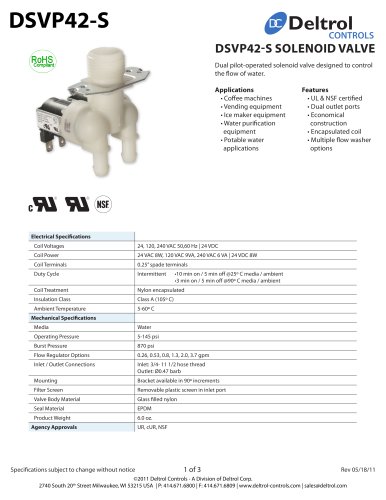
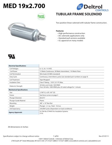
Specifications subject to change without notice 295 POWER RELAY 295 Applications Rev 11/07/06 Page 1 of 2 Power relay rated for 20/10 amps Tungsten @ 120/240 VAC (2.4 KW) switching on all contacts in a DPDT configuration. • Traffic controller equipment Features • 20 amp Tungsten switching on all contacts • Molded class F (155º C) coil construction • Contacts designed for superior switching performance • Contact wiping action results in long contact life • PPS molded panel for superior physical characteristics Rynite® is a registered trademark of EI du Pont de Nemours and Company Contact Data Expected Life • Configuration: DPDT • Electrical: 200,000 operations min. @ rated load • Material: Silver Cadmium Oxide • Mechanical: 5,000,000 operations min. @ no load • Size: 3/8” diameter Dielectric Strength Contact Ratings • Across open contacts: 1200 VRMS • Tungsten load rating • Contacts to coil: 2200 VRMS • 20 Amps @ 120 VAC (2.4 KW) • Contacts to frame: 2200 VRMS • 10 Amps @ 240 VAC (2.4 KW) • Pole to pole: 2200 VRMS Coil Data Mechanical Data • Nominal input voltage: 120/110 VAC, 60/50 Hz • Operating position: Any • Nominal coil power: 7.0 VA • Mounting: Cinch-Jones 2408 8 pin socket or equiv. • Coil resistance: 970 Ohms ±10% • Terminals: 0.250” x 0.055” (6.35mm x 1.40 mm) • Coil insulation: Molded Rynite® class F system • Insulation material: Thermoplastic 94V-O rating • Insulation resistance: 100 Megohms minimum • Cover material: Clear Polycarbonate 94V-2 rating • UL insulation system file No: E74443 • Cover protection category: 40 IP rating Operate Data • Weight: 7.0 oz. (198 grams) approx. • Pull-in voltage: 75% of nominal voltage Agency Information • Drop-out voltage: 30% of nominal voltage • UL recognized file No.: E37066 (US & Canada) • Operate time: 20 ms approx. • NEMA: Exceeds NEMA Standard TS 2-2003 • Release time: 20 ms approx. • D.O.T. Approvals: Temperature Data • Operating ambient: -40ºC to +65ºC • Storage ambient: -40ºC to +130ºC
Open the catalog to page 1
Specifications subject to change without notice 295 Rev 11/07/06 Page 2 of 2 Outline Dimensions (Dimensions shown in inches and [millimeters] Wiring Diagram (Viewed from pin end]
Open the catalog to page 2All Deltrol Controls catalogs and technical brochures
 DSVP40-S
4 Pages
 DSVP10
5 Pages
 Solenoids
6 Pages
 Hose Sets
3 Pages
 Relays
6 Pages
 MED 20x2_0
3 Pages
 DSVP16N
3 Pages
 Solenoid Data Sheet Catalog
114 Pages
 DSVP12N Dispense Valve
7 Pages
 Dispensing Valves Catalogue
4 Pages
 C-6 C-Frame Solenoid
4 Pages
 C-7 C-Frame Solenoid
4 Pages
 C-8 C-Frame Solenoid
4 Pages
 C-15 C-Frame Solenoid
4 Pages
 C-9 C-Frame Solenoid
4 Pages
 D-11 D-Frame Solenoid
4 Pages
 D-17 D-Frame Solenoid
4 Pages
 D-22 D-Frame Solenoid
4 Pages
 D-28 D-Frame Solenoid
4 Pages
 D-30 D-Frame Solenoid
4 Pages
 D3-HD D-Frame Solenoid
4 Pages
 D4-HD D-Frame Solenoid
4 Pages
 D-4 D-Frame Solenoid
4 Pages
 PS-75 D-Frame Solenoid
4 Pages
 D-90 D-Frame Solenoid
4 Pages
 Solenoid Catalogue
6 Pages
 Inlet Valve Catalogue
4 Pages
 Relay Catalogue
6 Pages
 DSVP14N Dispense Valve
5 Pages
 DSVP15N Dispense Valve
6 Pages
 DSV43N Inlet Valve
3 Pages
 D-70 D-Frame Solenoid
4 Pages
 D-50 D-Frame Solenoid
4 Pages
 D-2 D-Frame Solenoid
4 Pages
 C-5 C-Frame Solenoid
4 Pages
 C-4 C-Frame Solenoid
4 Pages
 DSVP42-S Inlet Valve
3 Pages
 DSVP40-S Inlet Valve
3 Pages
 DSVP40-R Inlet Valve
3 Pages
 DSVP10N Dispense Valve
5 Pages
 Hose Set Data Sheet
3 Pages
 DSVP11N Dispense Valve
7 Pages
 Latching Relays 166ML
2 Pages
 Power Relays 900 series
2 Pages
 Power Relays 177 series
1 Page
 Latching Relays 105ML
2 Pages
 Latching Relays 101ML
2 Pages
 Power Relays 375 series
2 Pages
 Power Relays 270/275 series
2 Pages


- Valve
- Control valve
- Water valve
- Electrically operated valve
- Gas solenoid valve
- NC solenoid valve
- 2-way solenoid valve
- Direct-operated solenoid valve
- Switching relay
- Water solenoid valve
- Air solenoid valve
- Pilot-operated solenoid valve
- NO solenoid valve
- Flow control valve
- Electromechanical relay
- 3-way solenoid valve
- DC electromechanical relay
- Solenoid
- Plastic solenoid valve