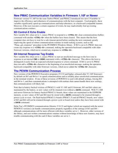
Digital Counter/Tachometer H7CC
1 /64Pages
Digital Counter/Tachometer H7CC
1 /64Pages
Catalog excerpts

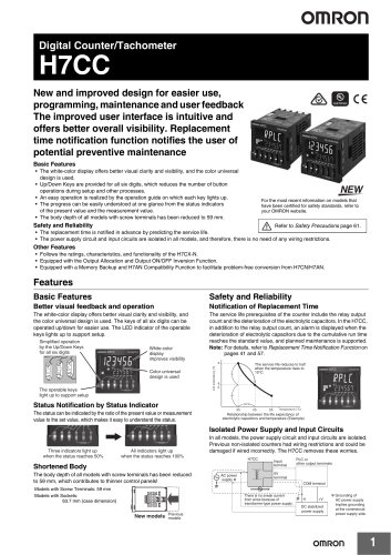
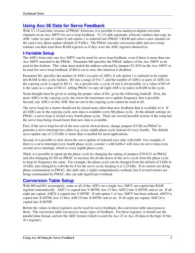
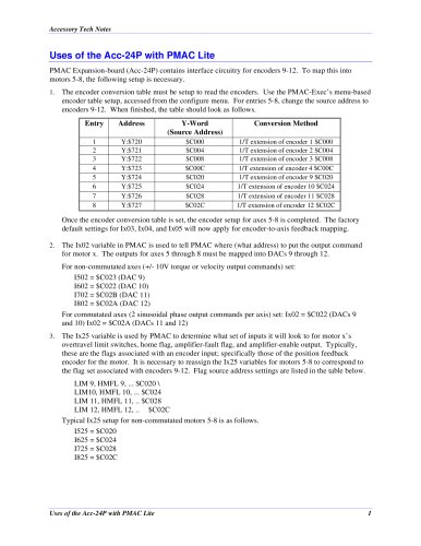
Digital Counter/Tachometer New and improved design for easier use, programming, maintenance and user feedback The improved user interface is intuitive and offers better overall visibility. Replacement time notification function notifies the user of potential preventive maintenance Basic Features • The white-color display offers better visual clarity and visibility, and the color universal design is used. • Up/Down Keys are provided for all six digits, which reduces the number of button operations during setup and other processes. • An easy operation is realized by the operation guide on which each key lights up. • The progress can be easily understood at one glance from the status indicators of the present value and the measurement value. • The body depth of all models with screw terminals has been reduced to 59 mm. For the most recent information on models that have been certified for safety standards, refer to your OMRON website. Refer to Safety Precautions page 61. • The replacement time is notified in advance by predicting the service life. • The power supply circuit and input circuits are isolated in all models, and therefore, there is no need of any wiring restrictions. Other Features • Follows the ratings, characteristics, and functionality of the H7CX-N. • Equipped with the Output Allocation and Output ON/OFF Inversion Function. • Equipped with a Memory Backup and H7AN Compatibility Function to facilitate problem-free conversion from H7CN/H7AN. Features Basic Features Better visual feedback and operation Notification of Replacement Time The white-color display offers better visual clarity and visibility, and the color universal design is used. The keys of all six digits can be operated up/down for easier use. The LED indicator of the operable keys lights up to support setup. The service life prerequisites of the counter include the relay output count and the deterioration of the electrolytic capacitors. In the H7CC, in addition to the relay output count, an alarm is displayed when the deterioration of electrolytic capacitors due to the cumulative run time reaches the standard value, and planned maintenance is supported. Note: For details, refer to Replacement Time Notification Function on pages 41 and 57. Simplified operation by the Up/Down Keys for all six digits White-color display improves visibility The operable keys light up to support setup Status Notification by Status Indicator Color universal design is used The service life reduces to half when the temperature rises to 10°C. The status can be indicated by the ratio of the present value or measurement value to the set value, which makes it easy to understand the status. Relationship between the life expectancy of electrolytic capacitors and temperature (Example) Isolated Power Supply and Input Circuits Three indicators light up when the status reaches 50% All indicators light up when the status reaches 100% In all models, the power supply circuit and input circuits are isolated. Previous non-isolated counters had wiring restrictions and could be damaged if wired incorrectly. The H7CC removes these worries. H7CC Shortened Body The body depth of all models with screw terminals has been reduced to 59 mm, which contributes to thinner control panels! Models with Screw Terminals: 59 mm Models with Sockets: 63.7 mm (case dimension) Input terminal 0V terminal COM terminal There is no sneak current from wires because of transformer-type power supply. Previous models PLC or other output terminals DC stabilized power supply * Grounding of AC power supply implies grounding at the commercial p
Open the catalog to page 1
Other Features Equipped with a Key Protect Function Any abnormality in the device due to malfunctioning or setting errors can be prevented. Follows the Ratings, Characteristics, and Functionality of the H7CX-N The H7CC follows the ratings, characteristics, and functionality of the H7CX-N. Other than the H7CC-A8D, all models are equipped with power supply to external devices, which reduces the load on wiring. Output Allocation Function The allocation of outputs 1 and 2 (OUT 1 and OUT2) can be changed. In the conventional 2-stage output models, output 1 (OUT1) was fixed as SPST, and output 2 (OUT2)...
Open the catalog to page 2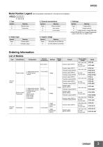
Model Number Legend (Not all possible combinations of functions are available.) 2. External connections 3. Settings Symbol * The H7CC-R11WD is a 1-stage (2 inputs and outputs) rather than a 2-stage counter. 4. Output type 5. Supply voltage Ordering Information List of Models Type External connections Preset counter 1-stage preset counter Total and preset counter Preset counter/ Tachometer 1-stage preset counter 2-stage preset counter Total and preset counter Batch counter Dual counter Twin counter Tachometer Screw terminals 1 stage (2 inputs and outputs) Display digits
Open the catalog to page 3
Soft Cover
Open the catalog to page 4
H7CC-AD Digital Counter • Equipped with a replacement time notification function. • The white-color display further improves visibility, and the color universal design is used. The Up/Down Keys make it easier to use the Counter. • Compatible with the ratings, characteristics, and functionality of the H7CX-N. For the most recent information on models that have been certified for safety standards, refer to your OMRON website. *1.1-stage preset counter and total counter functionality. *2. Do not use the output from an inverter as the power supply.The ripple must be 20% maximum for DC power. *3....
Open the catalog to page 5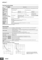
Tachometer Function Ratings * Refer to the Life-test Curve. Life-test Curve (Reference Values) Resistive load Inductive load A current of 0.15 A max. can be switched at 125 VDC (cos^=1) and current of 0.1 A max. can be switched if L/R=7 ms. In both cases, a life of 100,000 operations can be expected.
Open the catalog to page 6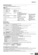
Applicable Standards Approved safety standards cULus (or cURus): UL508/CSA C22.2 No. 14 *1 EN 61010-1 (IEC 61010-1): Pollution degree 2/overvoltage category II EAC RCM B300 PILOT DUTY 1/4 HP 120 VAC, 1/3 HP, 240 VAC, 3 A, 250 VAC/30 VDC resistive load VDE0106/part100 (EMI) EN61326-1 *2 Emission Enclosure: (EMS) Immunity ESD: Immunity RF-interference: Immunity Conducted Disturbance: Immunity Burst: Immunity Surge: Immunity Voltage Dip/Interruption: 4 kV contact discharge; 8 kV air discharge 10 V/m (Amplitude-modulated, 80 MHz to 1 GHz) 3 V/m (Amplitude-modulated, 1.4 G to 2 GHz) 1 V/m (Amplitude-modulated,...
Open the catalog to page 7All Delta Tau catalogs and technical brochures
 TURBO PMAC2 VME ULTRALITE
7 Pages
 TURBO PMAC2 REALTIME EXPRESS
3 Pages
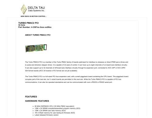 TURBO PMAC2 PCI
7 Pages
 TURBO PMAC VME
6 Pages
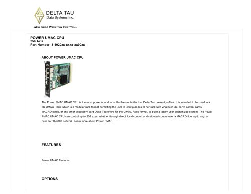 POWER UMAC CPU 256 Axis
4 Pages
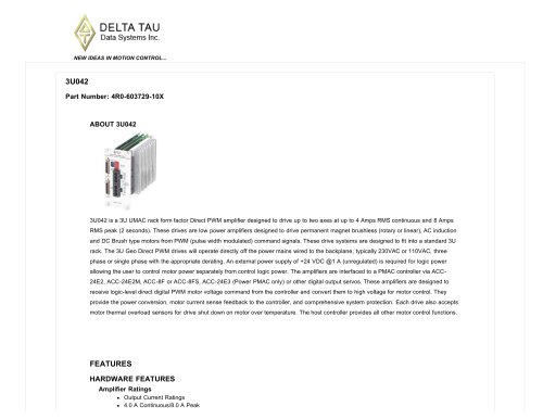 3U042
3U0424 Pages
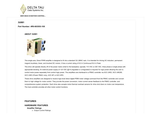 3U081
3U0814 Pages
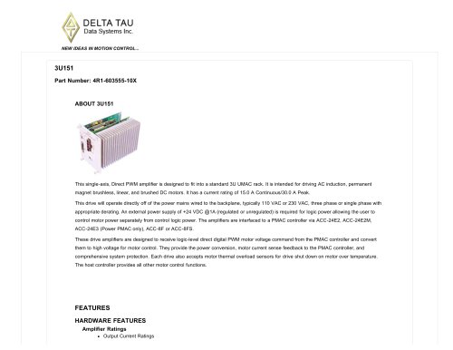 3U151
3U1514 Pages
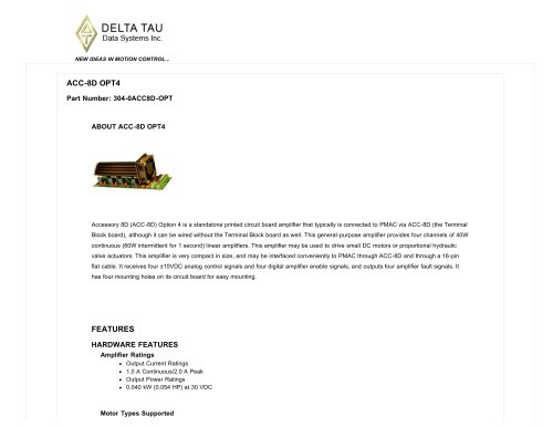 ACC-8D OPT4
3 Pages
 ACC-8D OPT4A
3 Pages
 ADVANTAGE 900 BASIC PACKAGE
3 Pages
 PMAC MINI PCI 8 Axis
7 Pages
 PMAC PCI 8 Axis
7 Pages
 PMAC PCI LITE 8 Axis
7 Pages
 PMAC VME 8 Axis
6 Pages
 PMAC2A PC/104
6 Pages
 POWER UMAC
4 Pages
 TURBO UMAC
6 Pages
 PMAC-NC PRO2 RUNTIME
3 Pages
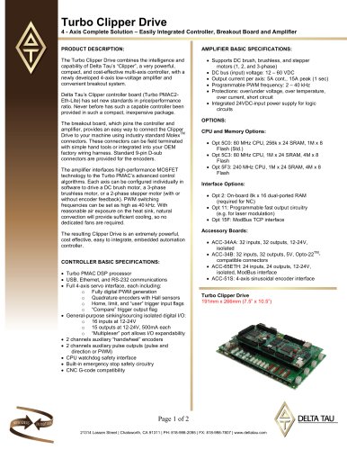 Turbo Clipper Drive
2 Pages
 Battery Issues with PMAC ISA
5 Pages
 Digital IO accessories
2 Pages
 MLDT Sensor
1 Page
 Slow communications
1 Page


- Servo-amplifier
- Remote I/O
- DC servo-amplifier
- AC servo-amplifier
- Brushless servo drive
- Digital servo-amplifier
- Electronic counter
- Electronic amplifier
- Multi-axis positioning controller
- CNC
- Current amplifier
- Ethernet positioning controller
- DC motion controller
- EtherCAT positioning controller
- Compact motion control card
- PWM servo-drive
- I/O system
- Servomotor positioning controller
- Integrated positioning controller