Catalog excerpts

DEIF A/S Application The loss of mains relay type LMR-111D forms part of a complete DEIF series of relays for protection and control of generators. This relay is applied for protection of synchronous generators, running in parallel with the mains. A mains failure will be detected, provided a disconnection at an arbitrary point of the network results in a swift change of the generator frequency (vector shift). An opening signal is then transmitted to the mains circuit breaker, and the generator will thus be protected against damages caused by an automatic reconnection to the high-voltage network. The LMR-111D will on the other hand not detect the normal relatively slow and acceptable changes of the frequency of the network (the mains). Furthermore, separation of a generator from the mains in case of mains failure is also stipulated as a condition in most national rules for connection of synchronous generators to the mains. Regarding Great Britain, see Engineering Recommendation G59. Measuring principle The relay supervises the angular velocity of the phases of the mains. The velocity is supervised by comparing the times for the latest two full cycles with the times for the full cycles of the previous 4th and 5th period. After 5 periods have passed (after connection to the mains) the relay will thus have performed the first measurement. After this the LMR-111D will within one period detect a vector shift. This method of measurement (comparing periods 1 and 2 with periods 4 and 5) ensures correct detection of a vector shift occurring very close to the zero crossing of the AC voltage. If the difference between the measurements exceeds the set point, the output is activated. Within 30 ms (inclusive of contact delay), an opening signal is transmitted to mains circuit breaker, and the LED marked "MAINS FAIL" is lit. The set point value is set on the front of the relay by means of a potentiometer marked “SENS”. The LMR-111D is provided with 1 reset input connected to contacts to the generator circuit breaker and to the mains circuit breaker. These 2 contacts should close when their respective circuit breaker is opened. When the RESET (22-23) is activated, the LMR-111D will not detect a possible mains failure. This function ensures that the relay is only active when both circuit breakers are closed and the generator thus is running in parallel with the mains. On receipt of a reset signal (transmitted by the mains circuit breaker auxiliary contact during opening of its circuit breaker), an internal timer is started. When this expires (after 2 s), the opening signal to the mains circuit breaker is cancelled, and the LED “MAINS FAIL” is switched off. The LMR-111D is provided with an adjustable initialising timer, which is activated on cancellation of the reset signal (closing of circuit breakers). When this timer expires, the LMR-111D is activated and the LED “Supervision” is lit. The time delay is set on the front of the relay by means of the potentiometer "Delay". Relay outputs The LMR-111D is provided with 2 output contacts (with common set points), either normally energised or normally de-energised. The contacts may be set to open or to close on activation. Normally energised contact Recommended for warning and alarm purposes. In case of an auxiliary supply drop-out, the contact is immediately activated. Normally de-energised contact Recommended for regulating and control purposes. An auxiliary supply failure will not result in an unwanted activation of the contact. Power-up circuit The relays are provided with a 200 ms power-up circuit, ensuring the correct function of the relay on connection of the auxiliary voltage. Note: Normally energised contacts are not activated (contact does not open/close) until 200 ms after connection of the auxiliary voltage. ANSI code 78 Loss of mains relay Type LMR-111D uni-line 4921240214D • Detection of vector shift • Mains disconnection on mains failure • Ensures no asynchronous reconnection • LED indication of fault condition • LED indication for activated relay • 35 mm DIN rail or base mounting LMR-111D
Open the catalog to page 1
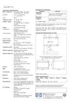
Technical specifications Meas. voltage (Un): See supply voltage - AC ranges UL/cUL listed: 57.7…450V AC Overload: 1.2 x Un, continuously, 2 x Un for 10 s Load: 2kÙ/V Frequency range: 40...45...65...70Hz “RESET” inputs: Input voltage: 18…250V AC/DC for “activated” condition Input impedance: 100kÙ Output: 2 change-over switches Contact type: Relays B + C: Normally energised (“NE”), or normally de-energised(“ND”) Contact ratings: 250V AC/24V DC, 8A (200 x 103 change-overs at resistive load) UL/cUL listed: Resistive load only Contact voltage: Max. 250V AC/150V DC Response time: <30 ms...
Open the catalog to page 2All DEIF catalogs and technical brochures
-
TRI-2
9 Pages
-
EQ96-sw4, EQ96-sw7, VDQ96-sw
4 Pages
-
CGC 400
10 Pages
-
AGC-4 Mk II
4 Pages
-
IMD 100
12 Pages
-
KBU
9 Pages
-
ASR
77 Pages
-
DCP2
4 Pages
-
DBC-1
15 Pages
-
Battery chargers TOP
3 Pages
-
AGC-4
30 Pages
-
Alarm panel – type AL8-2
8 Pages
-
Shunt resistors
2 Pages
-
ENGINE & GEN-SET CONTROLS
2 Pages
-
G59 protection relay package
3 Pages


