
Catalog excerpts

DBC-1 DEIF Battery Charger 12/24 V-5/10 A-115/230 V High MTBF > 60,000 h at 40°C Temperature range -25°C to +70°C Overvoltage protected Boost/equalisation functionality Failure alarm functionality DEIF A/S · Frisenborgvej 33 · DK-7800 Skive · Tel.: +45 9614 9614 · Fax: +45 9614 9615 · info@deif.com · www.deif.com
Open the catalog to page 1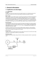
General information 1. General information 1.1 Application and advantages 1.1.1 Application DC supply The DBC-1 can be used as DC supply due to the low ripple of maximum 1.3%. Automatic recovery and protection against overload, short circuit and reverse polarity are standard functionalities of the DBC-1. Battery charger DBC-1 is ideal for the use as battery charger. The general recommendation for charging lead (Pb) batteries is a voltage ripple of maximum 2-5%, where the maximum voltage ripple for DBC-1 is 1.3%. It is designed to charge both lead-acid and gel batteries. The recommended...
Open the catalog to page 3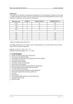
General information Voltage drop The charger can be adjusted to compensate the voltage drop in the wiring between the battery and the charger. Please notice that the current is only 50% of the nominal current if the boost/equalisation function is used. Examples of voltage drop can be found in the table below. Wire size, mm2 * Based on threaded copper wire at 20°C. The voltage drop formula is: dV = length x current x cable resistance x 2, thus the double current or double length will also double the voltage drop. Example: 1.5 mm2, 5 m, 10A => dV = 1.2 V Setting for Pb battery charging: 27.6...
Open the catalog to page 4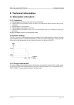
Technical information 2. Technical information 2.1 Description of functions 2.1.1 Protections ● ● Protected against continuous short-circuit and no-load operation Protected against reverse battery polarity connection, and automatically restarts operation after the fault is removed ● Protected against over-temperature ● Protected against undervoltage on line input ● Protected against overvoltage on output. The unit shuts itself down when an overvoltage on output terminals arises. An alarm condition occurs in any of the above cases. 2.1.2 Power derating The DBC-1 series has a high temperature...
Open the catalog to page 5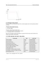
Technical information Inom Imax 2.1.4 Charger Failure Alarm These units have a dry contact alarm output which is closed (energised) under normal operating conditions (no failure). The alarm contact is steady open when: ● Failure on the line input or input fuse ● No output voltage. The alarm contact will work intermittent when: ● Failure caused by battery reverse polarity connection ● Overvoltage condition on output terminals. (Note: when overvoltage is detected while battery is connected, the alarm relay is open and locked in this position until the battery is disconnected) 2.1.5 LED...
Open the catalog to page 6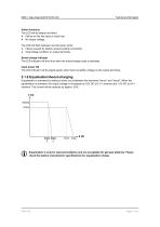
Technical information Alarm functions The LED will be steady red when: ● Failure on the line input or input fuse ● No output voltage. The LED will flash between red and green when: ● Failure caused by battery reverse polarity connection ● Overvoltage condition on output terminals. Boost-charge indicator The LED indicator will turn blue when the boost-charge mode is activated. Input power OK The LED indicator will be steady green when there is healthy voltage on the output terminals. 2.1.6 Equalisation/boost-charging Equalisation is activated by making a short circuit between the terminals...
Open the catalog to page 7
Technical information 2.2 Technical specifications 2.2.1 General data Duty ratio Continuous duty is allowed Protected against continuous short-circuit No-load operation Protected against continuous no-load operation DIN-rail, EN 50022-35 or 4 pcs. Ø4.5 mm holes for screw mounting.To obtain optimum cooling, it is imperative to comply with the specified installation position, where the terminals are at the bottom. If the mounting differs from this, a reduction in output must be expected, depending on the ambient temperature. If placed in conditions with vibrations, it might be necessary to...
Open the catalog to page 8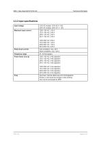
Technical information 2.2.2 Input specifications Input voltage Maximum input current Peak inrush current Cold conditions: max. 20 A Warm conditions: max. 100 A Frequency range Input fuse: internal safety fuse (not exchangeable). If blown, it will cause the charger to stop working. Can only be exchanged by DEIF.
Open the catalog to page 9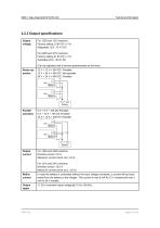
Technical information 2.2.3 Output specifications Output voltage For 1205 and 1210 versions: Factory setting 13.8V DC +/-1% Adjustable 12.6...15.1V DC For 2405 and 2410 versions: Factory setting 27.6V DC +/-1% Adustable 25.2...30.2V DC (Can be adjusted with a trimmer potentiometer at the front) Series operation 12 V + 12 V = 24V DC: Possible 12 V + 24 V = 36V DC: Not possible 24 V + 24 V = 48V DC: Possible DBC-1 Parallel operation 5 A + 5 A = 10A DC Possible 5 A + 10 A = 15A DC Possible 10 A + 10 A = 20A DC Possible DBC-1 Output current For 1205 and 2405 versions: Nominal current: 5.0 A...
Open the catalog to page 10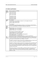
Technical information 2.2.4 Other specifications Noise Line regulation: All products have output regulation of maximum 1% in the range of line input of 115V AC models: 115V AC ±15% 230V AC models: 230V AC ±15% Load regulation: All products have output load regulation of maximum 1% in the range of no load to full load. <2 ms at a load distribution of 10 to 90% from rated current, peaks <2% IEC/EN 61000-6-4 vers. 115 V and 230 V IEC/EN 61000-6-1 vers. 115 V and 230 V IEC/EN 61000-6-2 vers. 115 V and 230 V RFI suppression: According to EN55011 class B Static discharge ESD: 4 kV contact...
Open the catalog to page 11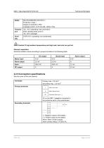
Technical information IEC EN 60950/IEC EN 61010-1 Protection: Class I Degree of protection: IP20 Leakage current: <0.75 mA (50…60Hz ± 5%) -25...70°C (operating, free convection) Note: derating starts at 60°C -40...85°C (storage) Caution! If high ambient temperature and high load, heat sink can get hot. Galvanic separation Electrical isolation values according to groups are listed in the following table: DC output Boost input Alarm output Mains input Alarm output 2.2.5 Connection specifications See the cover of the unit (imprint). Terminals Primary terminals - Mains Line input. - Mains...
Open the catalog to page 12All DEIF catalogs and technical brochures
-
TRI-2
9 Pages
-
EQ96-sw4, EQ96-sw7, VDQ96-sw
4 Pages
-
CGC 400
10 Pages
-
AGC-4 Mk II
4 Pages
-
IMD 100
12 Pages
-
KBU
9 Pages
-
ASR
77 Pages
-
DCP2
4 Pages
-
Battery chargers TOP
3 Pages
-
AGC-4
30 Pages
-
Alarm panel – type AL8-2
8 Pages
-
Shunt resistors
2 Pages
-
ENGINE & GEN-SET CONTROLS
2 Pages
-
G59 protection relay package
3 Pages


