
Catalog excerpts

4921230002D ? Compact Q96 design > S ? Extremely easy push-button programming (no jumpers or the like) ? Individual programming of each input: - N/O or N/C, time delay, alarm inhibit, output and cable supervision ? Up to 5 units in master/slave configuration ? Clear identification of first alarm received in case of successive alarms > DEIF A/ size="-2">
Open the catalog to page 1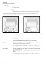
The alarm panel AL-8 is provided with: ? 8 alarm inputs ? 3 relay outputs: - 1 output for connection of horn and - 2 outputs used for transmission of group alarms, selective disconnection of faulty equipment, etc. The alarm panel is suitable to switchboards in industrial and marine plants for alarm and control purposes. It is CE marked for residential, commercial and light industry plus industrial environment. Alarm inputs: The alarm panel is provided with 8 alarm inputs for connection of external mechanical alarm contacts. These 8 inputs are individually > programmable for N/O or N/C alarm...
Open the catalog to page 2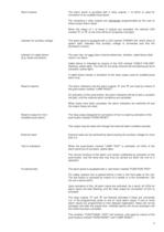
Alarm outputs: The alarm panel is provided with 3 relay outputs, 1 of which is used for connection to an audible/visual alarm. The remaining 2 relay outputs are individually programmable by the user to follow certain alarm inputs. When the relays of 1 of these 2 outputs are activated, the relevant LED marked "A" or "B" on the front will be lit constantly (red light). Indicator for auxiliary voltage: The alarm panel is equipped with a LED marked "POWER ON" which when lit (green light) indicates that auxiliary voltage is connected and that the processor is active. Indicator for cable failure:...
Open the catalog to page 3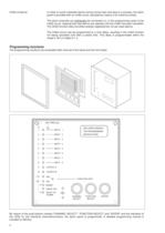
Inhibit of alarms: In order to avoid unwanted alarms during normal start and stop of a process, the alarm panel is provided with an inhibit circuit, activated by means of an external contact. The alarm channels can individually be connected (i.e. in the programming cycle) to the inhibit circuit, implying that new alarms are rejected until the inhibit has been cancelled. The inhibit function does not affect already registered but not yet reset alarms. The inhibit circuit may be programmed to a time delay, resulting in the inhibit function not being cancelled until after a preset time. This...
Open the catalog to page 4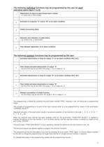
1 Registration of alarm at open/closed alarm contact - i.e. either N/C or N/O contact 2 Activation of output(s) "A" and/or "B" on an alarm condition 3 Inhibit of incoming alarm 4 Detection and indication of cable failure - e.g. broken wire, or termination 5 Time delayed registration of an alarm condition > 1 Activation/deactivation of relay for output "a" on an alarm condition (N/O, N/C) 2 Time limited activation/deactivation of output "A" - the time limit may be set within the range 1..10 s in steps of 1 s 3 Activation/deactivation of relay for output "B" on an alarm condition (N/O, N/C) 4...
Open the catalog to page 5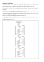
By means of connections for jumper cables on the rear of the alarm panel, up to 5 alarm units may be connected together. In this configuration the alarm unit with no plug in X2 will act as "master" and the remaining as "slave" units. Upon registration of an alarm condition in a "slave" unit, the relay outputs for horn of both the "slave" unit and the "master"unit are activated, whereas the relay outputs "A" and "B" are activated locally irrespective of the "master"/"slave" configuration. When connected in "master"/"slave" configuration, alarms and relay output for horn may be cancelled...
Open the catalog to page 6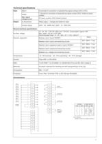
Input Alarm: 8 channels for connection of potential-free signal contacts (N/O or N/C). Inhibit: 1 channel for connection of potential-free signal contact (N/O). Inhibit at closed contact Max. signal voltage/current 6V (open contact), 6mA (closed contact) Output A, B and horn: Relay output, 1 change-over switch for each Contact rating: 250V - 2A - 400W (AC). 250V - 1A - 50W (DC) General technical specifications Auxiliary voltage 12 - 24 - 48 - 110V DC 25% (min. 10V DC). Consumption: approx. 6W Max. ripple: 10% pp, to IEC 688 Recommended fuses: 12 - 24 - 48V: 1A T, 110V: 150mA T Galvanic...
Open the catalog to page 7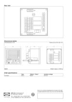
All dimensions in mm Panel cut-out: 92 x 92 +0.4 AL8-2 Weight: Approx. 0.390 kg > Type Master / Slave Auxiliary voltage Example: AL8-2 Master 24V DC > Due to our continous development we reserve the right to supply equipment which may vary from the described. DEIF A/S , Frisenborgvej 33 DK-7800 Skive, DenmarkTel.: +45 9614 9614, Fax: +45 9614 9615 E-mail: deif@deif.com, URL: www.deif.com size="-1">
Open the catalog to page 8All DEIF catalogs and technical brochures
-
TRI-2
9 Pages
-
EQ96-sw4, EQ96-sw7, VDQ96-sw
4 Pages
-
CGC 400
10 Pages
-
AGC-4 Mk II
4 Pages
-
IMD 100
12 Pages
-
KBU
9 Pages
-
ASR
77 Pages
-
DCP2
4 Pages
-
DBC-1
15 Pages
-
Battery chargers TOP
3 Pages
-
AGC-4
30 Pages
-
Shunt resistors
2 Pages
-
ENGINE & GEN-SET CONTROLS
2 Pages
-
G59 protection relay package
3 Pages


