
Catalog excerpts
DATA SHEET AGC PM Automatic Genset Controller, Plant Management • Management of up to 992 gensets • Island and parallel operation • Plant black start capabilities • Fuel-optimised control • Integrated genset protection DEIF A/S · Frisenborgvej 33 · DK-7800 Skive Tel.: +45 9614 9614 · Fax: +45 9614 9615 info@deif.com · www.deif.com
Open the catalog to page 1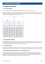
1. Application information 1.1 General information 1.1.1 A control system The AGC Plant Management is a control system that changes the way that we normally look at genset control. The AGC Plant Management is a plant control system that not only handles genset controls but also has built-in functions that are designated towards utility requirements, plant design, commissioning tools, maintenance and last but not least, a fuel-efficient way of ensuring that the required plant set point always will be fulfilled. 1.1.2 Cost-optimised design The AGC Plant Management can use the plant’s...
Open the catalog to page 3
When the AGC Plant Management operates in island mode, it offers a new way of sharing load: asymmetrical load sharing. Instead of running all generators on the same effort level, which will result in increased fuel consumption, asymmetrical load sharing will load the generators in a cascade. As one generator reaches its fuel-optimised set point, the next generator will start up and begin to take load. If necessary, the load sharing generators can use the system's spinning reserve. By doing so, the system becomes capable of maintaining the majority of generators at their optimum set points...
Open the catalog to page 4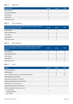
Single genset Genset modes Island operation X Fixed power/base load X Peak shaving X Load takeover X Mains power export X Table 1.3 Power management DATA SHEET 4921240420E UK Page 5 of 20
Open the catalog to page 5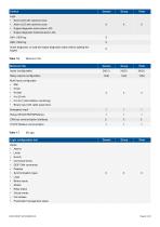
Logs: • Event LOG with real-time clock • Alarm LOG with real-time clock XXX • Engine diagnostic active alarm LOG • Engine diagnostic historical alarm LOG Inputs: Alarms Limits Events Command timers DEIF CAN commands Displays Synchronisation types Logic Binary inputs Modes Relay status Virtual events Fail classes Power/plant management status Logic configuration tool DATA SHEET 4921240420E UK Page 6 of 20
Open the catalog to page 6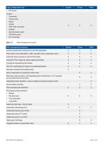
Logic configuration tool • EIC events Outputs: • Commands • Virtual events • Relays • Inhibits XXX • DEIF CAN commands • Displays • Synchronisation types • GOV/AVR control • EIC commands Plant (group) priority selection: • Manual • Running hours • Fuel optimisation • Load profile Safety stop (fail class = trip and stop) Asymmetric load sharing (LS) Independent group power control Independent group PF control Independent group var control Global plant CAN flags Integrated software comparability check DATA SHEET 4921240420E UK Page 7 of 2
Open the catalog to page 7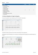
Emulation Genset Group Plant Available emulators: • Power/var/PF emulator • Motor emulator • Generator emulator • EIC data emulator XXX • Digital input emulator • Analogue input emulator • Plant emulator • Mains voltage/frequency emulator • Load emulator The setup of the application is easily configured using a PC and the DEIF PC utility software. The application drawing is programmed to the controller, and the plant layout is then programmed. The configuration tool will automatically turn into a supervision module afterwards with the possibility to see summarised values from the...
Open the catalog to page 8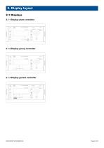
A&G°iRtesfAfesfigsmsf!? o PFCoortml O Woflt*B« support SalfCIhackCfc O 2.1.3 Display genset controller A<§G - PSms MmsgafsssBf O YoflkwrAtaran Salt Cfriock Ok O
Open the catalog to page 9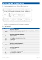
: The numbers in the drawing above refer to the slot numbers indicated in the tables below. 2 Terminal 29-36, communication, inputs/outputs H2 Modbus RTU (RS-485) H5.2 Plant Management communication, CAN port C H12.2 Plant Management communication, CAN port C and D 3 Terminal 37-64, inputs/outputs/load sharing Standard 13 x digital inputs; 4 x relay outputs DATA SHEET 4921240420E UK Page 10 of 20
Open the catalog to page 10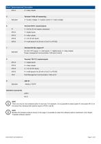
Standard 3 * busbar voltage; 3 * busbar current; 3 * mains voltage Standard ^ to 36 V DC supply; 3 * multi-inputs; 7 * digital inputs; 4 * relay outputs Power management communication, CAN port A and B H5.8 Plant Management communication, CAN port C Standard - Modbus TCP/IP INFO There can only be one hardware option in each slot. For example, it is not possible to select option H2 and option M13.2 at the same time, because both options require a PCB in slot #2. INFO Besides the hardware options shown on this page, it is possible to select the software options mentioned in the...
Open the catalog to page 11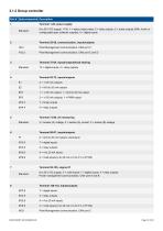
3.1.2 Group controller Slot # Option/standard Description 1 Terminal 1-28, power supply Standard 8 to 36 V DC supply, 11 W; 1 × status output relay; 5 × relay outputs; 2 × pulse outputs (kWh, kvarh or configurable open collector outputs); 5 × digital inputs Terminal 29-36, communication, inputs/outputs H5.2 Plant Management communication, CAN port C Plant Management communication, CAN port C and D Terminal 37-64, inputs/outputs/load sharing Standard 13 × digital inputs; 4 × relay outputs Terminal 73-89, AC measuring Standard 3 × busbar (A) voltage; 3 × busbar (A) current; 3 × busbar (B)...
Open the catalog to page 12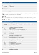
H5.2 J1939 engine communication and MTU (ADEC/MDEC), CAN port C H12.2 J1939 engine communication and MTU (ADEC/MDEC), CAN port C and D Standard 13 x digital inputs; 4 x relay outputs Active power load sharing; reactive power load sharing EF6 2 x +/-25 mA outputs; 1 x PWM output DATA SHEET 4921240420E UK Page 13 of 20
Open the catalog to page 13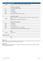
8 to 36 V DC supply, 5 W; 1 * magnetic pickup (MPU); 3 * multi-inputs; 7 * digital inputs; 4 * relay Standard outputs Power management communication, CAN ports A and B 8 Terminal 126-133, inputs/outputs H5.8 J1939 engine communication and MTU (ADEC/MDEC), CAN port C Standard - Modbus TCP/IP INFO There can only be one hardware option in each slot. For example, it is not possible to select option H2 and option M13.2 at the same time, because both options require a PCB in slot #2. INFO Besides the hardware options shown on this page, it is possible to select the software options...
Open the catalog to page 14All DEIF catalogs and technical brochures
-
TRI-2
9 Pages
-
EQ96-sw4, EQ96-sw7, VDQ96-sw
4 Pages
-
CGC 400
10 Pages
-
AGC-4 Mk II
4 Pages
-
IMD 100
12 Pages
-
KBU
9 Pages
-
ASR
77 Pages
-
DCP2
4 Pages
-
DBC-1
15 Pages
-
Battery chargers TOP
3 Pages
-
AGC-4
30 Pages
-
Alarm panel – type AL8-2
8 Pages
-
Shunt resistors
2 Pages
-
ENGINE & GEN-SET CONTROLS
2 Pages
-
G59 protection relay package
3 Pages


