
Catalog excerpts
DATA SHEET Automatic Genset Controller, AGC-4 ● ● ● ● ● ● Single or synchronising gensets Power plant control Fast synchronising Control and protection Customised logic and control SW emulation of application DEIF A/S · Frisenborgvej 33 · DK-7800 Skive · Tel.: +45 9614 9614 · Fax: +45 9614 9615 · info@deif.com · www.deif.com Document no.: 4921240400I SW version: 4.2x.x or later
Open the catalog to page 1
Application information 1. Application information 1.1 General information 1.1.1 Application The Automatic Genset Controller, AGC, is a control unit containing all necessary functions for protection and control of a genset. It can be used as a single unit for one genset, or a number of AGCs can be connected in a complete power management system for synchronising projects, islanded or paralleled to the mains. The AGC contains all necessary 3-phase measuring circuits, and all values and alarms are presented on the sunshine proof LCD display. The AGC is a compact all-in-one unit designed for...
Open the catalog to page 3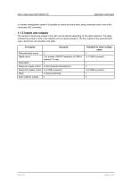
Application information In a power management system it is possible to control the entire plant, being connected only to one of the connected AGC controllers. 1.1.3 Inputs and outputs The number of inputs and outputs in the AGC can be tailored depending on the option selection. This table includes the number of I/Os in the standard unit (no options present). The four outputs of the governor/AVR card in slot #4 are not included in the table. In-/outputs Available for other configuration Multi-selectable inputs Digital inputs 2 for breaker ON/OFF feedbacks (4 if MB is present)/1 E-stop Relays...
Open the catalog to page 4
Application information 1.1.4 Included functions General functions Short time parallel Temperature-dependent cooling down Time-based cooling down Emergency cooling down kVArh meter Day/week/month/total Engine running hours counter, emergency, normal Start attempt counter Maintenance counter Breaker operation counter Free PC utility SW (Windows) Permission settings in PC utility SW for limited SCADA access Password-protected setup Power derate Nominal settings for rental gensets Battery test, crank or asymmetry Mains support (frequency and voltage) Fuel pump logic Engine block heater control...
Open the catalog to page 5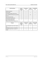
Control functions Application information Start/stop sequences Close before excitation (fast synchro.) Stop coil with wire break Relay outputs for speed control Event log with real-time clock Alarm log with real-time clock Battery crank test log with real-time clock Logic configuration tool for plant customising Selectable input events, e.g. plant status Selectable output events, e.g. plant commands
Open the catalog to page 6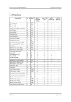
Application information Reverse power Short circuit Voltage-dependent overcurrent Unbalanced voltage Unbalanced current Busbar/mains overvoltage Busbar/mains undervoltage Load shed, three levels via current via busbar frequency via overload via fast overload Busbar/mains overfrequency Multi-config. inputs with wire break alarms, three inputs Emergency stop High auxiliary supply Generator breaker external trip Tie/mains breaker external trip Synchronisation failure alarms Breaker open failure Breaker close failure Breaker position failure Close before excitation failure
Open the catalog to page 7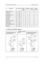
Application information Phase sequence error Deload error Crank failure Running feedback error Start failure Stop failure Stop coil, wire break alarm Engine heater Battery test alarm Fuel fill check 1.1.6 Single line application diagrams Standard, 1 controller 1. Automatic mains failure and fixed power/base load 3. Peak shaving, load takeover and mains power export Mains Mains Display Consumers Generator breaker (GB) Consumers Generator breaker (GB)
Open the catalog to page 8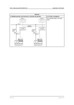
Application information Optional 4. Multiple gensets, load sharing (1 controller per genset) Display 1 5.-9. Power managment See separate page in this data sheet Busbar Analogue loadsharing Generator breaker (GB 1)
Open the catalog to page 9
kvar SHARE MULTI INPUTS CANbus Modbus Profibus COMMON FOR E-STOP E-STOP STOP COIL AGC-4 data sheet 4921240400 UK Application information This terminal strip overview shows the terminals of an AGC with commonly used HW options. The diagram might not reflect your actual unit due to different option configuration.
Open the catalog to page 10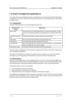
Application information 1.2 Power management applications The purpose of the power management system is to implement one control system that controls all breakers and all gensets. This can for instance be for fuel optimised purposes, for easy implementation of plant logic or for safety reasons. 1.2.1 Application The plant modes supported by the power management options are: Standard plant modes Island mode Power plant with synchronising generators or a stand-alone generator. Can also be used in critical power plants with a start signal from an external (ATS) controller Automatic Mains...
Open the catalog to page 11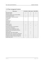
Application information 1.2.3 Power management functions PM functions Multi-master system Redundant CANbus Short-time parallel (in same controller (MB/TB)) Load-dependent start/stop Priority selection, manual and automatic Running hours Load profile Manual Fuel optimised Ground relay Load management Secured mode (start one extra generator) Quick setup for rental groups Heavy consumer control/generator request Asymmetric LS for optimal generator load level Mains feeder control, feeders paralleled Mains feeder control, main-tie-main for critical power Base load running for maintenance (island...
Open the catalog to page 12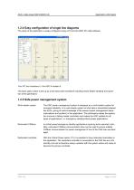
Application information 1.2.4 Easy configuration of single line diagrams The setup of the application is easily configured using a PC and the DEIF PC utility software. Your PC tool visualises it - the AGC-4 realises it. The basic plant control is set up by a few basic plant conditions including mains feeder handling and operation of the generators 1.2.5 Safe power management system Multi-master system The AGC power management system is designed as a multi-master system for increased reliability. In a multi-master system all vital data is transmitted between the AGCs, giving all units...
Open the catalog to page 13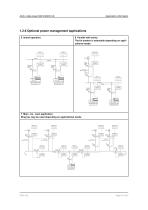
Application information 1.2.6 Optional power management applications 5. Island operation. 6. Parallel with mains. The tie breaker is selectable depending on applicational needs. Display mains Busbar CANbus Consumers Tie breaker (TB) Display 1 7. Main - tie - main application. Ring bus may be used depending on applicational needs.
Open the catalog to page 14All DEIF catalogs and technical brochures
-
TRI-2
9 Pages
-
EQ96-sw4, EQ96-sw7, VDQ96-sw
4 Pages
-
CGC 400
10 Pages
-
AGC-4 Mk II
4 Pages
-
IMD 100
12 Pages
-
KBU
9 Pages
-
ASR
77 Pages
-
DCP2
4 Pages
-
DBC-1
15 Pages
-
Battery chargers TOP
3 Pages
-
Alarm panel – type AL8-2
8 Pages
-
Shunt resistors
2 Pages
-
ENGINE & GEN-SET CONTROLS
2 Pages
-
G59 protection relay package
3 Pages


