SpiderGrip Section
1 /32Pages

SpiderGrip Section
1 /32Pages
Catalog excerpts
Spidergrip Geometric End Effector System Product Overview SpiderGrip Geometric End Effector Tooling System offers a standard cost effective solution by making it easy for each component to be replaced individually in the robotic cell, dramatically reducing production downtime and eliminating the need for a second end-effector. This system is crash test certified and features automatic optical & standard CMM validation points. Transition Junction Edge Component Collar Assembly Spidergrip modular components are easily configurable and offer high strength to weight ratios while maintaining dimensional accuracy after continuous minor collisions. The patented collar/key design and engineered breakaway base anchor provides quick crash recovery. Dimensions and technical information are subject to change without notice
Open the catalog to page 1
Spidergrip Geometric End Effector System Product Overview Most commonly used in: Heavy Duty Mid Mount Assembly Applications Fixture Welding Pick and Place Material Handling Geometric Fixtures Corner Junction Base Anchor Engineered Breakaway 82M Series Power Clamp Dimensions and technical information are subject to change without notice Markets Industrial Automotive Aerospace Appliance
Open the catalog to page 2
SpiderGrip End Effector Tooling Systems Spidergrip Tooling Components | Typical Application Build Examples Materials Handling End Effector Tooling System with RM4 Heavy Duty Mid-Mount Assembly (RM4-STS). Geometric End Effector Tooling System with Steel Frame Backbone. Weld Fixture Tooling System SpiderGrip Application Guide 900 Ø60 mm SpiderGrip Ø90 mm SpiderGrip (Not including SpiderGrip Components) Dimensions and technical information are subject to change without notice
Open the catalog to page 3
Dimensions and technical information are subject to change without notice
Open the catalog to page 4
SpiderGrip Mid Mount Assembly Spidergrip Tooling Components | Dimensions, How To Order Heavy-Duty Mid Mount Assembly Robot Interface Pattern Accessory (e.g. EPM-01) (Leave blank if NONE) Dimensions and technical information are subject to change without notice
Open the catalog to page 5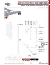
Spidergrip Mid Mount Accessory Plate Spidergrip Tooling Components | Dimensions, How To Order Accessory Mount Plate When ordering with Heavy Duty Mid Mount, please add designation “EPM-01” as shown RM4-STS-RXX-EPM-01 or add designation “EPM-BLK” to order blank RM4-STS-RXX-EPM-BLK To order separately use Model Number Model Number Weight CPI-BM2-EPM-xx .63 kg [1.39 lb] Dimensions and technical information are subject to change without notice
Open the catalog to page 6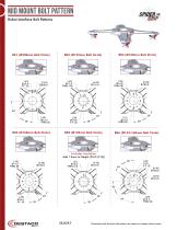
Mid Mount Bolt Pattern Robot Interface Bolt Patterns
Open the catalog to page 7
Mid Mount Bolt Pattern Includes Insulation Includes Insulation Includes Insulation R01 Robot Interface Bolt Patterns Includes Insulation
Open the catalog to page 8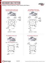
Mid Mount Bolt Pattern Spidergrip Tooling Components | Robot Interface Bolt Patterns R14 (Ø200mm Bolt Circle) (Ø125mm Pilot, 11mm Deep) R13 (Ø125/160mm Bolt Circle) (Ø110mm Pilot, 5.5mm Deep) Includes Insulation
Open the catalog to page 9
Spidergrip Mid Mount Anchor Spidergrip Tooling Components | Technical Specifications, Dimensions Ø60mm Mid Mount Anchor 40mm x 40mm Mounting Pattern - 50mm Face Offset Dimensions and technical information are subject to change without notice
Open the catalog to page 10
SPIDERGRIP MID MOUNT ANCHOR Spidergrip Tooling Components | Technical Specifications, Dimensions 060mm Base Anchor with 50mm Face Offset ALL OTHER PATENTS PENDING Engineered Breakaway Part Dimensions and technical information are subject to change without noti
Open the catalog to page 11
Spidergrip Mid Mount Anchor Spidergrip Tooling Components | Technical Specifications, Dimensions Ø70mm Base Anchor with 25mm Face Offset (6) Hole Mounting Pattern BREAKAWAY POINT (STS0025-NA-BA-1500 ONLY) *This Product is designed to breakaway at 1500 N*m [1106 ft-lb] Dimensions and technical information are subject to change without notice
Open the catalog to page 12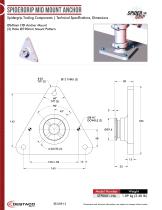
Spidergrip Mid Mount Anchor Spidergrip Tooling Components | Technical Specifications, Dimensions Ø60mm HD Anchor Mount (3) Hole Ø190mm Mount Pattern Dimensions and technical information are subject to change without
Open the catalog to page 13
SpiderGrip End Effector Tooling Systems Spidergrip Tooling Components | Assembly Instructions Model Number# STCCLR2-NA/90 Collar Assembly Model Number# STCXKEY-NA/90 X-Key Assembly M8-1.25 x 40mm Torque to 25 N*m [220 in-lb] (for Ø60mm) or 30 N*m [265 in-lb] (for Ø90mm) PATENT PENDING Assembly Instructions – First Assembly In many cases, it may be advantageous to assemble the appendage remotely and then once complete, mount the entire appendage assembly onto the mounting structure. Model Number# STS0016-NA(shown) or STS0017-90 Anchor Mount 1. Clean/Wipe and inspect ALL mating faces of all components...
Open the catalog to page 14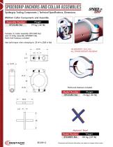
SpiderGrip Anchors and Collar Assemblies Spidergrip Tooling Components | Technical Specifications, Dimensions Ø60mm Collar Components and Assembly Assembly Number STCCLRX-NA Includes (1) Collar Assembly (STCCLR2-NA) and (1) X-Key Assembly (STCXKEY-NA). Patch-lock fasteners included. Max bolt torque when clamping to: 25 N*m [220 in-lbs] 69.00 4.0 US PATENT# 7,331,104 ALL OTHER PATENTS PENDING Patch-lock fasteners included. Material: Steel Model Number STCXKEY-NA EE-SGP-15 Dimensions and technical information are subject to change without notice
Open the catalog to page 15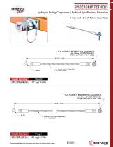
Spidergrip Tethers Spidergrip Tooling Components | Technical Specifications, Dimensions 9 inch and 16 inch Tether Assemblies FLAT WASHER IS REQUIRED FOR ALL M6 BOLTS M6-30mm SHCS PATCHLOCK (TO BE SUPPLIED BY END USER) FLAT WASHER IS REQUIRED FOR ALL M6 BOLTS 8.75" 3/16" M6-30mm SHCS PATCHLOCK (TO BE SUPPLIED BY END USER) 8.75" 3/16" 1/8" DIA NYLON SHIELDED 7-19 WIRE ROPE 1/8" DIA NYLON SHIELDED 7-19 WIRE ROPE FLAT WASHER IS REQUIRED FOR ALL M6 BOLTS M6-30mm SHCS PATCHLOCK (TO BE SUPPLIED BY END USER) FLAT WASHER IS REQUIRED FOR ALL M6 BOLTS M6-30mm SHCS PATCHLOCK (TO BE SUPPLIED BY END USER)...
Open the catalog to page 16
SpiderGrip Booms, Adaptors and Spacers Spidergrip Tooling Components | Technical Specifications, Dimensions Ø60mm Boom M6 tap holes along the boom are used to mount accessories Model Number Dimensions and technical infor
Open the catalog to page 17All DE-STA-CO catalogs and technical brochures
 CH
CH9 Pages
 VSA500
2 Pages
 ECOCUP
2 Pages
 AC-BT
AC-BT1 Page
 QC TP
QC TP15 Pages
 FUA Series Section
2 Pages
 Rotary Actuators Section
28 Pages
 G100 Section
12 Pages
 DPE Section
8 Pages
 Die Storage Section
4 Pages
 DBG Bag Gripper Section
22 Pages
 BodyBuilder Section
82 Pages
 Round Tooling Section
72 Pages
 Automatic Tool Changer Section
52 Pages
 Manual Tool Changer Section
2 Pages
 Robot Adapter Mounts
38 Pages
 215 Series
2 Pages
 213 Series
2 Pages
 205 Series
2 Pages
 5305, 5310 Series
2 Pages
 305, 307, 309 Series
2 Pages
 HEAVY DUTY CLAMPS
2 Pages
 Series 3011
1 Page
 Series 301, 311
1 Page
 Series 324, 334, 344, 374
4 Pages
 Series 323, 331, 341
4 Pages
 Pull Action Latch Clamps
2 Pages
 Series 3051
1 Page
 Series 506
3 Pages
 Series 504
3 Pages
 Series 2027
2 Pages
 Series 2037
2 Pages
 Series 205
2 Pages
 Series 2017
2 Pages
 Series 2005
2 Pages
 Series 305, 307, 309
2 Pages
 Series 215
2 Pages
 Series 213
2 Pages
 206-SS
2 Pages
 Series 206
2 Pages
 Rotary Actuators
58 Pages
 Camco Product
263 Pages
 Parallel Grippers
278 Pages
 Clamping Technology Catalog
485 Pages
 DSC Robohand Automation Catalog
629 Pages
 Modular Conveyor Systems
32 Pages
 DSC Conveyors Catalog
132 Pages
 DSC Robohand Automation Catalog
658 Pages
 DSC Vacuum Products Catalog
52 Pages
 Automation Power Clamps Catalog
34 Pages
 Pneumatic Swing Clamps Catalog
24 Pages
 Standard Power Clamps Catalog
28 Pages
 Workholding Catalog
343 Pages


Archived catalogs
 griper references
18 Pages


- Rail conveyor
- Cylinder
- Actuator
- Linear actuator
- Horizontal conveyor
- Double-acting cylinder
- Hydraulic cylinder
- Pneumatic gripper
- Pneumatic manipulator
- Toggle clamp
- Materials handling manipulator
- Chain conveyor
- Single-acting cylinder
- Work conveyor
- Parallel gripper
- 2-jaw gripper
- Modular conveyor
- Manipulator with gripping tool
- Multi-channel manifold