CH
1 /9Pages

CH
1 /9Pages
Catalog excerpts
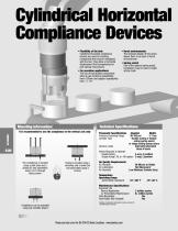
* Harsh environments: The enclosed design of this series allows them to be used in harsh environments. * Spring assist: Due to the optional spring assist, compliance may be used in single acting mode. Cylindrical Horizontal Compliance Devices * Flexibility of the tool: Cylindrical Horizontal compliance devices are used for inserting components that may be misaligned with the tool. They allow a horizontal displacement that compensates for part placing inaccuracies. * For precision applications: The use of high quality components allow to get centering repeatability from 0.02mm and angular repeatability from +/- 10°. Mounting Information: Technical Specifications: It is recommended to use the compliance in the vertical axis only 80 ' f The compliance is located using a pilot boss and a dowel pin and assembled using 4 or 6 through body screws Tooling is located using a centering and a dowel pin and assembled using 4 screws Pneumatic Specifications Imperial Metric Pressure Operating Range 30-100 psi 2-7 bar Cylinder Type Double acting or double acting spring assist or single acting spring return Dynamic seals Internally lubricated Buna-N seals Valves Required to Operate Double Acting 4-way, 2 position Single Acting (-RL or -RA option) 3 way, 2 position Air Quality Requirements Air Filtration 40 Micron or Better Air Lubrication Not Necessary* Air Humidity Low Moisture Content (dry) Temperature Operating Range Joints Nitrile (standard) -10°~180° F -25°~80° C Compliance can be operated using top manifold airport Maintenance Specifications** Expected Life Normal Application 3 million cycles w/ Preventative Maintenance 6+ million cycles Field Repairable Yes Seal Repair Kits Available Yes *Addition of lubrication will greatly increase service life **See Maintenance Section
Open the catalog to page 1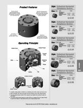
Product Features Spring Assist Quality Components Spring assist option allows to center the tool (RA) or to release the tooling (RL). It also allows the use in single acting mode Made from aluminum alloy hard coat anodization. Main components are made of hardened and precision ground steel Style- Cylindrical Horizontal Compliance Devices CH-50 Size-50 Style: Misalignment Capability: ± 0.118 in. ± 3 mm Maximum Payload: 4.4 lbs. 2 Kg Weight: 0.43 lbs. 0.195 Kg See Page Style- Cylindrical Horizontal Compliance Devices CH-80 Size-80 Style: Misalignment Capability: ± 0.197 in. ± 5 mm Maximum Payload:...
Open the catalog to page 2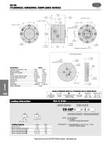
CH-50 CYLINDRICAL HORIZONTAL COMPLIANCE DEVICES 36.5 1.437 - I: Tool Plate Option UNLESS OTHERWISE NOTED ALL TOLERANCES ARE AS SHOWN BELOW Imperial in. Dimensions are symmetrical about centerline Third Angle Projection All Dowel Holes are SF (Slip Fit). Metric Threads Locational Tolerance Course Pitch ±.0005" or [±.013mm] BASIC MODEL Loading Capacity SPRING ASSIST MISALIGNMENT SPRING RA Tool Recentering RL Tool Release __ Leave Blank. No Spring Option (standard) Maximum Tensile T Maximum Breakaway Compressive C Maximum Breakaway Moment Mx Maximum Breakaway Moment My Maximum Breakaway Moment Mz...
Open the catalog to page 3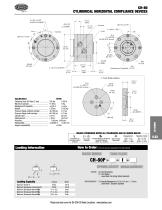
CH-80 CYLINDRICAL HORIZONTAL COMPLIANCE DEVICES 2 x [M4 x 5 DP] (supplied plugged) - I: Tool Plate Option [5.5] 4 x Ø0.217 for [M5] SHC screws UNLESS OTHERWISE NOTED ALL TOLERANCES ARE AS SHOWN BELOW Imperial in. Dimensions are symmetrical about centerline Third Angle Projection All Dowel Holes are SF (Slip Fit). Metric Threads Locational Tolerance Course Pitch ±.0005" or [±.013mm] BASIC MODEL TOOL PLATE SPRING ASSIST MISALIGNMENT SPRING RA Tool Recentering RL Tool Release __ Leave Blank. No Spring Option (standard) Loading Capacity Maximum Tensile T Maximum Breakaway Compressive C Maximum Breakaway...
Open the catalog to page 4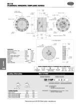
CH-110 CYLINDRICAL HORIZONTAL COMPLIANCE DEVICES 16.0 0.630 - I: Tool Plate Option UNLESS OTHERWISE NOTED ALL TOLERANCES ARE AS SHOWN BELOW Imperial in. Dimensions are symmetrical about centerline Third Angle Projection All Dowel Holes are SF (Slip Fit). Metric Threads Locational Tolerance Course Pitch ±.0005" or [±.013mm] BASIC MODEL TOOL PLATE SPRING ASSIST MISALIGNMENT SPRING RA Tool Recentering RL Tool Release __ Leave Blank. No Spring Option (standard) Loading Capacity Maximum Tensile T Maximum Breakaway Compressive C Maximum Breakaway Moment Mx Maximum Breakaway Moment My Maximum Breakaway...
Open the catalog to page 5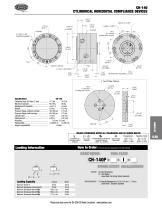
- I: Tool Plate Option [140.0] Ø5.512 UNLESS OTHERWISE NOTED ALL TOLERANCES ARE AS SHOWN BELOW Imperial in. Dimensions are symmetrical about centerline Third Angle Projection All Dowel Holes are SF (Slip Fit). Metric Threads Locational Tolerance Course Pitch ±.0005" or [±.013mm] BASIC MODEL TOOL PLATE SPRING ASSIST MISALIGNMENT SPRING RA Tool Recentering RL Tool Release __ Leave Blank. No Spring Option (standard) Loading Capacity Maximum Tensile T Maximum Breakaway Compressive C Maximum Breakaway Moment Mx Maximum Breakaway Moment My Maximum Breakaway Moment Mz How to Order: (Order Accessories...
Open the catalog to page 6
CH-165 CYLINDRICAL HORIZONTAL COMPLIANCE DEVICES 24.0 0.945 [Ø8 H9 x 16 DP] - I: Tool Plate Option [11.0] 4 x Ø 0.433 for [M10] SHC srews UNLESS OTHERWISE NOTED ALL TOLERANCES ARE AS SHOWN BELOW Imperial in. Dimensions are symmetrical about centerline Third Angle Projection All Dowel Holes are SF (Slip Fit). Metric Threads Locational Tolerance Course Pitch ±.0005" or [±.013mm] BASIC MODEL TOOL PLATE SPRING ASSIST MISALIGNMENT SPRING RA Tool Recentering RL Tool Release __ Leave Blank. No Spring Option (standard) Loading Capacity Maximum Tensile T Maximum Breakaway Compressive C Maximum Breakaway...
Open the catalog to page 7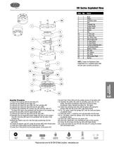
CH Series Exploded View Item Qty Name 1 1 Body NOTE: Contact the Robohand Sales Department for a complete spare parts list with order numbers and prices. 87 Assembly Procedures 1) Press-in the bushing (#8) into the body (#1) 2) Insert the pins (#65) into the body (#1) 3) Lubricate and insert the pins (#62) into the bushings (#8) 4) Lubricate and insert the keys (#9) into the pins (#62) 5) Lubricate and assemble the crossed ring (#5) onto the body (#1). The keys (#9) have to be positioned into the slots of the crossed ring 6) Insert the pins (#61) into the output flange (#6) 7) Lubricate...
Open the catalog to page 8All DE-STA-CO catalogs and technical brochures
 VSA500
2 Pages
 ECOCUP
2 Pages
 AC-BT
AC-BT1 Page
 QC TP
QC TP15 Pages
 FUA Series Section
2 Pages
 Rotary Actuators Section
28 Pages
 G100 Section
12 Pages
 DPE Section
8 Pages
 SpiderGrip Section
32 Pages
 Die Storage Section
4 Pages
 DBG Bag Gripper Section
22 Pages
 BodyBuilder Section
82 Pages
 Round Tooling Section
72 Pages
 Automatic Tool Changer Section
52 Pages
 Manual Tool Changer Section
2 Pages
 Robot Adapter Mounts
38 Pages
 215 Series
2 Pages
 213 Series
2 Pages
 205 Series
2 Pages
 5305, 5310 Series
2 Pages
 305, 307, 309 Series
2 Pages
 HEAVY DUTY CLAMPS
2 Pages
 Series 3011
1 Page
 Series 301, 311
1 Page
 Series 324, 334, 344, 374
4 Pages
 Series 323, 331, 341
4 Pages
 Pull Action Latch Clamps
2 Pages
 Series 3051
1 Page
 Series 506
3 Pages
 Series 504
3 Pages
 Series 2027
2 Pages
 Series 2037
2 Pages
 Series 205
2 Pages
 Series 2017
2 Pages
 Series 2005
2 Pages
 Series 305, 307, 309
2 Pages
 Series 215
2 Pages
 Series 213
2 Pages
 206-SS
2 Pages
 Series 206
2 Pages
 Rotary Actuators
58 Pages
 Camco Product
263 Pages
 Parallel Grippers
278 Pages
 Clamping Technology Catalog
485 Pages
 DSC Robohand Automation Catalog
629 Pages
 Modular Conveyor Systems
32 Pages
 DSC Conveyors Catalog
132 Pages
 DSC Robohand Automation Catalog
658 Pages
 DSC Vacuum Products Catalog
52 Pages
 Automation Power Clamps Catalog
34 Pages
 Pneumatic Swing Clamps Catalog
24 Pages
 Standard Power Clamps Catalog
28 Pages
 Workholding Catalog
343 Pages


Archived catalogs
 griper references
18 Pages


- Rail conveyor
- Actuator
- Linear actuator
- Horizontal conveyor
- Clamping device
- Double-acting cylinder
- Hydraulic cylinder
- Pneumatic gripper
- Pneumatic manipulator
- Toggle clamp
- Materials handling manipulator
- Chain conveyor
- Single-acting cylinder
- Work conveyor
- Parallel gripper
- 2-jaw gripper
- Modular conveyor
- Manipulator with gripping tool
- Multi-channel manifold