- Company
- Products
- Catalogs
- News & Trends
- Exhibitions
DT1400
1 /72Pages
DT1400
1 /72Pages
Catalog excerpts

Operating Instructions
Open the catalog to page 1
6. Display and manual controls
Open the catalog to page 2
7.8. Enable / disable displaying the leader zeros (06. menu item) 35 7.10. The number of averaged measurements (08. menu item)... 38 7.16. Assignment analog output low (start) value to display value 7.17. Assignment analog output high (end) value to display value
Open the catalog to page 3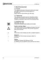
1. About this document1.1. Function This operating instructions manual has all the information you need for quick set-up and safe operation of DT1400 xx xx. Please read this manual before you start setup. This operating instructions manual is directed to trained personnel. The contents of this manual should be made available to these personnel and put into practice by them. This symbol indicates helpful additional information. This symbol informs you of a dangerous situation that could occur. Ignoring this cautionary note can impair the person and/or the instrument. The dot set in front indicates...
Open the catalog to page 4
All operations described in this operating instructions manual must be carried out only by trained and authorized specialist personnel. For safety and warranty reasons, any internal work on the instruments must be carried out only by DATCON personnel. The DT1400 xx xx Limit switch enable process variable 0-20 mA, 4-20 mA, 0-10 V, 0-5 V, 2-10 V to be displayed in engineering units on the control panel. Detailed information on the application range of the instrument is available in chapter „Product description”. 2.3. Warning about misuse Inappropriate or incorrect use of the instrument can give...
Open the catalog to page 5
Delivered items The scope of delivery encompasses: this operating instructions manual warranty 3.3. Operating principle Area of application The DT1400 xx xx Limit switch compares the 0-20 mA, 4-20 mA, 0-10 V, 0-5 V, 2-10 V input signal with the set values. When the input signal exceed one of the set values the instrument activates the corresponding SPDT relay contact. The DT1400 xx xx is also a process indicator and enable linear process variable to be displayed in engineering units on its 5 digit LED display. The instrument is available with the following output options (2 limit-relays are standard,...
Open the catalog to page 6
Oparating principle The input current or voltage to be measured is led to the 22 bit A/D converter through a protection and signal condition circuit. The digital output signal of the A/D converter is processed by a microcontroller. The microcontroller drives the 5 digit LED display, processes the front panel membrane keypad, drives the limit relays, the analogue output. Easy on-site configuration through the front panel membrane keypad is a major advantage of the microcontroller-based technology. The configuration parameters: input signal selection, signal filtering, display scaling, decimal...
Open the catalog to page 7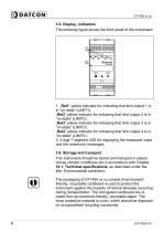
The following figure shows the front panel of the instrument: 1. „Rel1 ” yellow indicator for indicating that limit output 1 is in “on-state” (LIMIT1). „Rel2” yellow indicator for indicating that limit output 2 is in “on-state” (LIMIT2). „Rel3” yellow indicator for indicating that limit output 3 is in “on-state” (LIMIT3). „Rel4” yellow indicator for indicating that limit output 4 is in “on-state” (LIMIT4). 2. 5 digit 7 segment LED for displaying the measured value and the mnemonic messages. This instrument should be stored and transport in places whose climatic conditions are in accordance with...
Open the catalog to page 8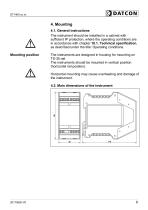
4. Mounting 4.1. General instructions The instrument should be installed in a cabinet with sufficient IP protection, where the operating conditions are in accordance with chapter 10.1. Technical specification, as described under the title: Operating conditions. Mounting position The instruments are designed in housing for mounting on TS-35 rail. The instruments should be mounted in vertical position (horizontal rail position). Horizontal mounting may cause overheating and damage of the instrument. 4.2. Main dimensions of the instrument
Open the catalog to page 9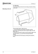
4.3. Mounting The following figure shows the mounting procedures (fixing on the rail): Mounting on the rail The mounting doesn’t need any tool. 1. Tilt the instrument according to the figure; put the instrument’s mounting hole onto the upper edge of the rail (figure step 1.). 2. Push the instrument’s bottom onto the bottom edge of the rail (figure step 2.), you will hear the fixing assembly closing. 3. Check the hold of the fixing by moving the instrument firmly.
Open the catalog to page 10
Always observe the following safety instructions: • Connect or disconnect only in the complete absence of line voltage • Take note the data concerning on the overcurrent protection in installation. • Use only a screwdriver with appropriate head Select connecting cable Take note the suitability of the connecting cable (wire cross-section, insulation, etc.). You may use either solid conductor or flexible conductor. In case of using flexible conductor use crimped wire end. In case of mains connection the wire cross-section should be 1.0 mm (min.). It’s an important rule that the power cables and...
Open the catalog to page 11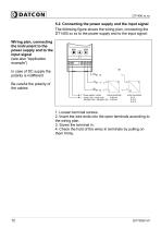
5.2. Connecting the power supply and the input signal The following figure shows the wiring plan, connecting the DT1400 xx xx to the power supply and to the input signal: Wiring plan, connecting the instrument to the power supply and to the input signal (see also “Application example”) In case of DC supply the polarity is indifferent Be careful the polarity of the cables 1. Loosen terminal screws. 2. Insert the wire ends into the open terminals according to the wiring plan. 4. Check the hold of the wires in terminals by pulling on them firmly.
Open the catalog to page 12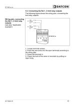
5.3. Connecting the Rel 1, 2 limit relay outputs The following figure shows the wiring plan, connecting the limit relay outputs: Wiring plan, connecting the Rel 1, 2 limit relay outputs (see also “Application example”) 1. Loosen terminal screws. 2. Insert the wire ends into the open terminals according to the wiring plan. 3. Screw the terminal in. 4. Check the hold of the wires in terminals by pulling on them firmly.
Open the catalog to page 13All Datcon Industrial Electronics Ltd. catalogs and technical brochures
 Leaflet of DT1122
2 Pages
 Leaflet of DT1102 V
2 Pages
 Leaflet of DT1102 ROOT
2 Pages
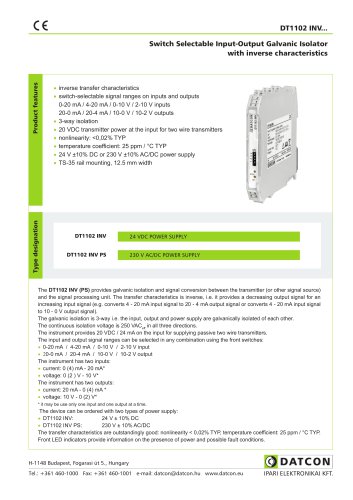 Leaflet of DT1102 INV
2 Pages
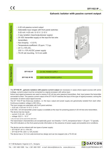 Leaflet of DT1102 IP
2 Pages
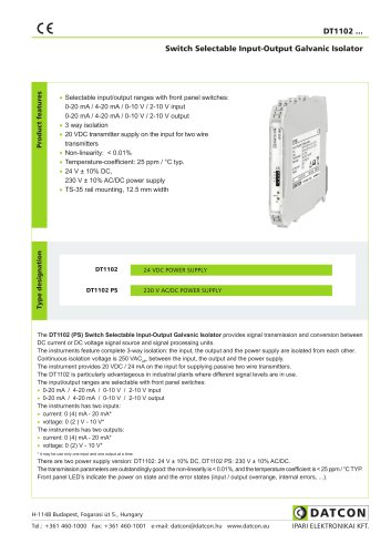 DT1102 Leaflet of product
2 Pages
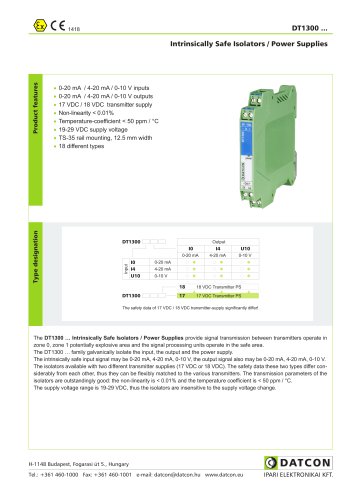 DT1300
2 Pages
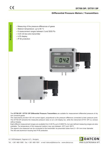 DT700 DP / DT701 DP
2 Pages


Archived catalogs
 DEMS5005
2 Pages


- DC power supply
- AC/DC power supply
- Pressure transmitter
- Analog pressure transmitter
- Digital pyrometer
- Power supply for industrial applications
- Digital indicator
- Waterproof pressure transmitter
- Industrial thermometer
- Panel panel meter
- DIN rail power supply
- Gas pressure transmitter
- Waterproof thermometer
- Sensitive element pressure transmitter
- IP65 pressure transmitter
- Temperature transmitter
- Differential pressure transmitter
- Piezoresistive pressure transmitter
- Power meter