- Catalogs
- Datalogic s.r.l.
- JadeTM X7
JadeTM X7
1 /8Pages

JadeTM X7
1 /8Pages
Catalog excerpts

JadeTM X7 Installing the Transition Plate The Transition Plate is an assembly bridging the gap between the two conveyor belts. The glass portion of the plate passes scanning illumination up from the Bottom Scanner and onto items passing over it on the conveyor. See Figure 1. Figure 1. The Transition Plate Assembly in its Mounted Position Transition Plate Design Features • • • • Allows leading edge of window to be mounted closer to belt for optimal item transfer. Adjustable window angle to fine tune item transfer. Lifting aid for easy window removal. Flexible mounting options. • Slotted mounting features for height adjustment. • +/- 3 mm of overall width tolerance. • Self-centering springs to locate window in optimal location in belt gap. Adjustable spring retention force. Additional adjustable magnetic retention force. Mount design allows for optimal mounting directly to conveyor belt frame. Mount design allows for wide takeaway belt. Integrated sensor that provides signal if transition plate is dislodged.
Open the catalog to page 1
Preparation for the Transition Plate Conveyor belts and other checkstand features are not included with the Portal Scanner and their installation details are not included with these instructions, however, Figure 10 specifies some important alignment details and dimensions concerning the relationship between the conveyor belts and the Transition Plate. The topic in these instructions: "Transition Plate Mounts" on page 4, describes how to perform the alignment using a custom Jade System Alignment tool. Also see Figure 9 for additional conveyor belt considerations. Figure 2 Transition Plate Location...
Open the catalog to page 2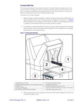
Conveyor Belt Gap If the conveyor belt gap (in the position where the Transition Plate is installed) is not in the correct location or the gap is too narrow, the bottom scanner performance will suffer. If the gap is too wide, the possibility of items getting stuck on the transition plate is increased, as well as the likelihood of small items falling through the gap. To position the conveyor belt gap: 1. When the gap is perfectly placed in relation to the arches and its width set at its optimal distance, the ‘nose’ of the Jade System Alignment Tool (item 1 of Figure 4) will exactly fit into the...
Open the catalog to page 3
The Transition Plate Assembly The Transition Plate assembly is comprised of the parts indicated in Figure 5. Figure 5. Transition Plate Components Glass Assembly Transition Plate Mounts Figure 6a shows details of Mounts A and B. When the transition plate glass is correctly installed in the mounts, a magnetic field is applied to a switch (Figure 6b) connected to each of the transition plate mounts (left and right sides). The transition plate mount electrical switch has the specifications described below. Transition Plate Mount Electrical Switch Contact Form SPDT ”Changeover” The common contact...
Open the catalog to page 4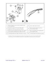
Mount using 4mm screw. Hole is slotted for positional adjustment. Switch signal leads (3 wires). Adjustment screw for Transition Plate angle Mounts clearly labeled ‘A’ and ‘B’ on front and back of each Mount must be supported from below. Two notches are provided for indexing lower support to mount. Wire routing features for routing wires out through the sides. Centering spring centers glass assembly on mounts. Transition plate mount electrical switch1 adjustment. Must have access from the top. 1. Connection of the transition plate sensor/switch to the conveyor belt control is the not covered...
Open the catalog to page 5
Transition Plate Mounts — continued The Transition Plate mounts must be attached to the conveyor belt carrier assembly as indicated in Figure 7. This is accomplished by securing each of them with a 4mm screw inserted through the hole shown as item 1 in Figure 6 and via the two indexing notches (shown as item 2 in Figure 6). It is the checkstand manufacturer’s responsibility to make provisions for these attachments. Figure 7 specifies pertinent dimensions when positioning the necessary supports. In the event that support of the mounts using their notches is not possible, two alternate mounting...
Open the catalog to page 6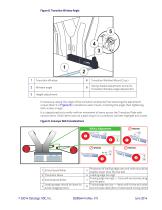
Figure 8. Transition Window Angle Transition Window Transition Window Mount (2 ea.) Window angle Spring-loaded adjustment screw for Transition Window angle adjustment Height adjustment If necessary, adjust the angle of the transition window by first loosening the adjustment screws (item 5 in Figure 8) in located on each mount, correcting the angle, then tightening both screws snugly. It is a good practice to verify uniform movement of items across the Transition Plate with various items. Small items such as a pack of gum or a candy bar will best highlight any issues. Figure 9. Conveyor Belt Considerations...
Open the catalog to page 7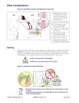
Other Considerations Figure 10. Liquid/Debris Collection and Aligning the Conveyor Belt Critical: Liquid and Debris Spillage Critical Measurement: Center to Belt Edge Measurement: Belt Height Difference Measurement: Space Between Belt Edges Debris Tray / Window Align Belt with Notches (located on Window Mask) Spillage Container [Not included with the Portal Scanner. Optionally supplied by the checkstand manufacturer.] Cleaning Whenever needed, lift off the transition plate glass and gently clean its top, bottom and sides (Figure 11) using paper towels or lint-free cleaning tissues dampened with...
Open the catalog to page 8Archived catalogs
 Heron series
2 Pages
 PowerScan® 7000 2D series
2 Pages
 Lynx? series
2 Pages
 Magellan? 800i series
2 Pages
 Gryphon? GPS4490 series
2 Pages
 Skorpio X3
8 Pages
 Elf
Elf16 Pages
 Falcon X3
12 Pages
 Rhino
Rhino4 Pages
 Gryphon I GM4100
2 Pages
 Magellan 3200VSi
2 Pages
 US18 Series
8 Pages
 DS-MOPA_DY
2 Pages
 DS-MOPA_M
2 Pages
 DM3610
2 Pages
 QuickScan I QM2400
2 Pages
 QuickScan I QBT2400
2 Pages
 Heron Instinctive Reader
2 Pages
 Catcher Presentation Scanner
2 Pages
 DS8100A Laser Scanner
2 Pages
 SC6000 Industrial Controller
2 Pages
 DX6400 - DX6500
2 Pages
 Lynx Hand Held 2D Reader
2 Pages
 Datalogic Jet PDA
2 Pages
 Unattended Scanning Systems
4 Pages
 Mobile Computers
4 Pages
 Heron G
2 Pages


- AMOT digital camera
- Visible imager
- AMOT CMOS camera
- AMOT industrial camera
- AMOT infrared camera
- Monitoring camera system
- Image processing camera module
- Monochrome camera module
- Waterproof camera module
- Compact imager
- Inspection imager
- Photoelectric sensor
- Rugged camera
- High-performance imager
- Smart camera
- Rectangular photoelectric sensor
- AMOT distance sensor
- Portable camera system
- Ethernet video camera
- Megapixel imager