- Catalogs
- Data Display GmbH
- G065VN01 V2-V540
G065VN01 V2-V540
1 /24Pages

G065VN01 V2-V540
1 /24Pages
Catalog excerpts
The information contained in this document has been carefully researched and is, to the best of our knowledge, accurate. However, we assume no liability for any product failures or damages, immediate or consequential, resulting from the use of the information provided herein. Our products are not intended for use in systems in which failures of product could result in personal injury. All trademarks mentioned herein are property of their respective owners. All specifications are subject to change without notice.
Open the catalog to page 1
1. Operating Precautions 1) Display area (Polarizer) of TFT-LCD Module is easily to be damaged, please be cautious and not to scratch it. 2) Be sure to power off your machine before connecting or disconnecting your signal cable to TFT-LCD Module. 3) Wipe off water drop on display area immediately. Long contact with water may cause discoloration or spots. 4) When the panel surface is soiled, wipe it with absorbent cotton or soft cloth. 5) Display area (Glass) of TFT-LCD Module may be broken or cracked if bump Module against hard object. 6) To avoid ESD (Electro Static Discharde) damage, be sure...
Open the catalog to page 4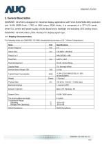
G065VN01 V2-V540 is designed for industrial display applications with VGA (640xRGBx480) resolution and 16.2M (RGB 6-bits + FRC) or 262k colors (RGB 6-bits). It is composed of a TFT-LCD panel, driver ICs, control and power supply circuits board and a backlight unit excluding LED driving circuit. G065VN01 V2-V540 offers LVDS interface for display signal input. The following items are G065VN01 V2-V540 characteristics summary at 25 °C(Room Temperature).
Open the catalog to page 5
The optical characteristics are measured under stable conditions at 25°C (Room Temperature). Note 1: Measurement method Equipment Pattern Generator, Power Supply, Digital Voltmeter, Luminance meter (SR_3 or equivalent) Aperture 1 ° with 50cm viewing distance Test Point Center measuring distance >n mil iiiiiiniMi MI IIIIIIIIIMI in iiiiiinii II >
Open the catalog to page 6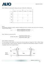
Note 2: Definition of 5 points position (Display active area: 132.48mm(W) x 99.36mm(H)) The luminance uniformity of 5 points is defined by dividing the maximum luminance value by the minimum luminance value at full white condition. _Maximum Brightness of five points_ Minimum Brightness of five points Note 4: Definition of contrast ratio (CR): Brightness @ "White" state Brightness @ "Black" state Note 5: Definition of response time: The output signals of photo detector are measured when the input signals are changed from "White" to "Black" (falling time) and from "Black" to "White" (rising time),...
Open the catalog to page 7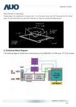
Note 6: Definition of viewing angle Viewing angle is the measurement of contrast ratio ^10, at the screen center, over 180° horizontal and 180° vertical range. The 180° horizontal (8L, 8R) and 180° vertical (ct>H, <$L) range are illustrated as following figure. Normal Line 3. Functional Block Diagram The following diagram shows the functional block of the G065VN01 V2-V540 color TFT/LCD module.
Open the catalog to page 8
4. Absolute Maximum Ratings Note 1: Maximum Wet-Bulb should be 39°C and no condensation. Note 2: Only operation is guaranteed. Optical performance should be evaluated at 25°c only. >n mil iiiiiiniMi MI IIIIIIIIIMI in iiiiiinii ii >
Open the catalog to page 9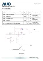
Note 1: Measurement condition: >n mil iiiiiiniMi MI IIIIIIIIIMI in iiiiiinii ii >
Open the catalog to page 10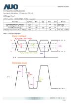
5.1.2 Signal Electrical Characteristics Input signals shall be low or Hi-Z state when VDD is off. LVDS signal (Note 1) Note 1: LVDS Signal Waveform. Single-end Signal
Open the catalog to page 11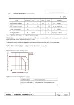
5.2. Backlight Specifications (1 rail version)
Open the catalog to page 12
6.1 Pixel Format Image Following figure shows the relationship between input signal and LCD pixel format. The following figures show the image seen from the front view. The arrow indicates the direction of scan. R/L=High; U/D=High Note 1: TFT-LCD interface signal description is shown in section 6.4.
Open the catalog to page 13
6.3 The Input Data Format SEL68 = "Low" or "NC" for 6 bits LVDS Input SEL68 = "High" for 8 bits LVDS Input Note 1: Output signals from any system shall be low or Hi-Z state when VDD is off.
Open the catalog to page 14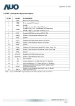
6.4 TFT- LCD Interface Signal Description Note 1: "Low" stands for 0V. "High" stands for 3.3V. "NC" stands for "No Connection". >n mil iiiiiiniMi MI IIIIIIIIIMI in iiiiiinii ii >
Open the catalog to page 15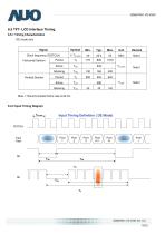
Note 1: Recommended frame rate is 60 Hz. 6.5.2 Input Timing Diagram Input Timing Definition ( DE Mode) >n mil iiiiiiniMi MI IIIIIIIIIMI in iiiiiinii ii >
Open the catalog to page 16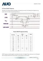
6.6 Power ON/OFF Sequence VDD power, LCD interface signals and backlight on/off sequence are shown in the following chart. Signals from any system shall be Hi-Z state or low level when VDD is off. Power ON/OFF sequence timing ON/OFF sequence should be applied to avoid abnormal function in the display. Please make sure to turn off the power when you plug the cable into the input connector or pull the cable out of the connector.
Open the catalog to page 17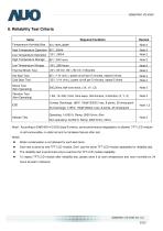
8. Reliability Test Criteria Items 40 High Temperature Operation 85 Low Temperature Operation High Temperature Storage 85 ____________________________ Temperature Humidity Bias Required Condition Thermal Shock Test Cold Start Test Shock Test (Non-Operating) Vibration Test (Non-Operating) 1.5G, 10~200~10Hz, Sine wave, 30mins/axis, 3 direction (X, Y, Z) /1 Hr (min.), power on/off per 5 minutes, repeat 5 times /1 Hr (min.), power on/off per 5 minutes, repeat 5 times Attitude Test Operating: 14,000 ft, Ramp: 2000 ft/min, 8hrs Non-operating: 40,000 ft, Ramp: 2000 ft/min, 24hrs Note1: According to...
Open the catalog to page 20
135.9 + 0.3 [Bezel Dpeninq Area] 1, Tolenrances unless narked are ±0,2nn 5EV ECN NO. DESCRIPTION SIGN IATE REV ECN NO. DESCRIPTION SIGN DATE
Open the catalog to page 21
10.1 Shipping Label (on the rear side of TFT-LCD display) Max. capacity: 80 TFT-LCD module per carton (40pcs * 2 layers) Outside dimension of carton: 425(L)mm* 386(W)mm* 430(H)mm
Open the catalog to page 22
11.1 Keen Edge Requirements There will be no keen edges or corners on the display assembly that could cause injury. There will be no carcinogenic materials used anywhere in the TFT-LCD module. If toxic materials are used, they will be reviewed and approved by the responsible AUO toxicologist. All components including electrical components that do not meet the flammability grade UL94-V1 in the TFT-LCD Module will complete the flammability rating exception approval process. The printed circuit board will be made from material rated 94-V1 or better. The actual UL flammability rating will be printed...
Open the catalog to page 23All Data Display GmbH catalogs and technical brochures
 ArtistaGUI
22 Pages
 SmartLED-III
18 Pages
 product catalog 2019
72 Pages
 POS-Line 61.0 / 24"
7 Pages
 POS-Line 54.5 / 21.5"
7 Pages
 POS-Line 43.94 / 17.3"
7 Pages
 POS-Line 48.3 / 19"
7 Pages
 POS-Line 38.1 / 15"
7 Pages
 XTRA-Line 46 LED
2 Pages
 XTRA-Line 27
4 Pages
 POS HB 1000 cd 138.7 / 54.6"
6 Pages
 POS HB 1000 cd 80.0 / 31.5"
6 Pages
 POS-Line 163.8 / 64.5"
6 Pages
 POS-Line 139.7 / 54.6"
9 Pages
 POS-Line 116.8 / 46"
9 Pages
 POS-Line 106.7 / 42"
9 Pages
 POS-Line 80.0 cm
9 Pages
 WEBPOStER Monitore
3 Pages
 TP-DD1010-A04
3 Pages
 TP - DD0500 - A02
3 Pages
 TP- DD0500 -A01
3 Pages
 LM240WU8- SLA2 -V551B
32 Pages

