- Company
- Products
- Catalogs
- News & Trends
- Exhibitions
DW500UB-2V
1 /9Pages

DW500UB-2V
1 /9Pages
Catalog excerpts

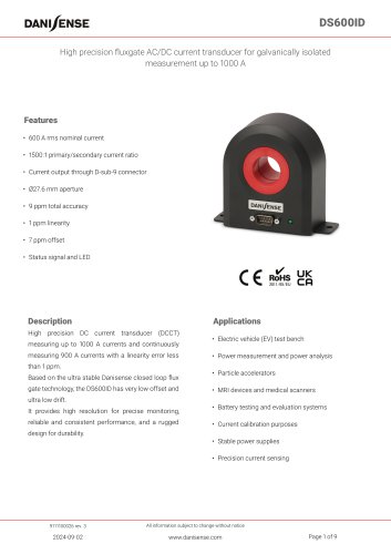
• Electric vehicle (EV) test bench • High frequency applications • Power measurement and power analysis • Precision drives • Battery testing and evaluation systems • Wide bandgap (WBG) SiC and GaN devices • Current calibration Features • 500 A rms nominal current • 2V output at 500 A through BNC connector • 24/30 mm aperture with/without plastic insert • Dedicated power supply included High precision wide bandwidth DC current transducer (DCCT) measuring up to 750 A currents and continuously measuring 500 A currents with a linearity error less than 15 ppm. Using a special high frequency transducer head, the DW500UB-2V has a very wide bandwidth up to 10 MHz. Phase compensation is made easy thanks to a near constant phase delay of around 12.5 ns, including a 2m coax cable. Based on the ultra stable Danisense closed loop flux gate technology, the DW500UB-2V has very low offset and ultra low drift. Built in a compact aluminium housing, it provides high resolution for precise monitoring, reliable and consistent performance, and a rugged design for durability. All information subject to change without notice
Open the catalog to page 1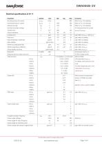
1 ppm nominal = 2 ^V secondary voltage. 2023-12-19 All information subject to change without notice www.danisense.com
Open the catalog to page 2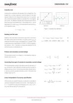
Linearity error Linearity error is defined as the deviation from a straight line. The straight line is a linear regression trend line based on the least squares method of the measurement points from 0 to positive max current and another trendline is calculated from 0 to negative max current. The difference between each measured point and the linear trend line is the linearity error. The linearity error eL can be expressed as (1), where Ireading is the measurement result and Ifitted is the regression value. Reading is the actual value measured at a given time. Full scale is the rated nominal value...
Open the catalog to page 3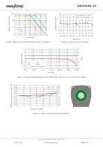
Conductor position All information subject to change without notice www.danisense.com
Open the catalog to page 4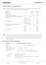
A When using REINFORCED insulated wire, all wiring must be insulated for the highest voltage used. When using BASIC insulated or uninsulated wire, follow the specified voltages in the table below: Connections: Mains AC cable and BNC connector Cleaning: The transducer should only be cleaned with a damp cloth. No detergent or chemicals should be used. All information subject to change without notice www.danisense.com
Open the catalog to page 5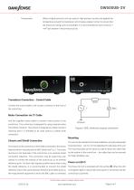
When multiple primary turns are used or high primary currents are applied the temperature around the transducer will increase, please monitor to ensure that the maximum ratings are not exceeded. It is recommended to have minimum 1 mm2 per ampere in the primary bus bar. Transducer Connection - Control Cable Connect the control cable to the circular connector on the front of Mains Connection via C7 Cable Use the supplied mains cable to connect mains power to the control box. The control box is designed for using universal mains 100-240Vac, 50-60Hz. The product is designed as a Class II product,...
Open the catalog to page 6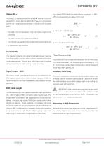
DW500UB-2V Status LED The Status LED is indicated with this symbol For a typical RG58 cable, the signal velocity is around v = 198 · . When the LED is ON (green light) it means that the cable to the transducer is connected, and the unit is ready for measurements. If the LED is OFF (no green • The cable from the transducer to the control box might not be connected • The current is out of the measurement range • Current have been applied to the busbar before powering the unit • An internal error has occurred Control Cable It is important that the 3m cable from the transducer must be connected to...
Open the catalog to page 7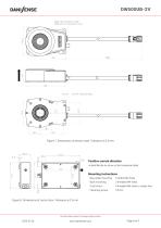
Ø24 with insulation tube Ø30 without insulation tube Positive current direc Figure 7: Dimensions of sensor head. Tolerance is 0.3 mm UNLESS OTHERWISE STATED THE BELOW APPLIES TOLERANCES BREAK CORNERS DRAWING NUMBER PART/ASSEMBLY NUMBER Is identified by an arrow on the transducer label 1:5 INSPECTIONS TOLERANCES ARE MARKED WITH: TREATMENT SURFACE ROUGHNESS Positive current direction 28/03/2022 FAZ DOC. STATUS Mounting instructions CHECKED DATE 21/11/2022 FAZ Base plateAPPR mounting: DEVELOPMENT 4 slotted M4 holes Back mounting: Control box : Mechanics layout for product datasheet Fastening torque:...
Open the catalog to page 8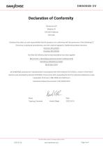
Declaration of Conformity Danisense A/S Malervej 10 DK-2630 Taastrup Dato: 15. November 2012 Declares that under our sole responsibility that this product is in conformity with the provisions of the following EC Directives, including all amendments, and with national legislation implementing these directives: Directive 2014/30/EU Directive 2014/35/EU And that the following harmonized standards have been applied EEN 61010-1 (Third Edition):2010, EN 61010-1:2010/A1:2019 EN 61010-2-030:2021/A11:2021 EN 61326-1:2013 All DANISENSE products are manufactured in accordance with RoHS directive 2011/65/EU....
Open the catalog to page 9All Danisense catalogs and technical brochures
 DS600ID
9 Pages
 DS400ID
9 Pages
 DS300ID
9 Pages
 DS200ID
9 Pages
 DT200ID
8 Pages
 DT100ID
8 Pages
 DT50ID
8 Pages
 DQ640ID-B
7 Pages
 DQ600ID-P1300
7 Pages
 DQ600ID
9 Pages
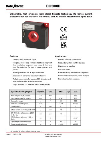 DQ500ID
7 Pages
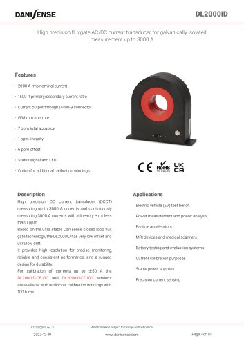 DL2000ID
10 Pages
 RCM Smart
10 Pages
 RCM Standard
9 Pages
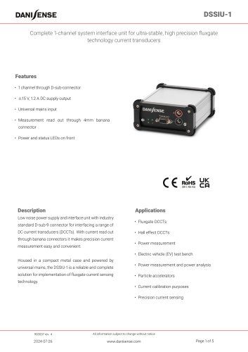 DSSIU-1
5 Pages
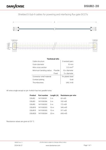 DSUB2-20
1 Page
 DSSIU-6-1U-V
8 Pages
 DSSIU-4-1U
6 Pages
 DS50ID
9 Pages
 DL2000UB-10V
9 Pages
 DL2000UB-1V
9 Pages
 DS300UB-1V
8 Pages
 DS300UB-10V
8 Pages
 DM1200ID-CD3000
7 Pages
 DN1000ID
9 Pages
 DM1200ID
8 Pages
 DSSIU-6-1U
7 Pages
 DR5000UX-10V/7500A
9 Pages
 DR10000IM
9 Pages
 DR5000IM
9 Pages
 Product Selection Guide
24 Pages
 DP50IP-B
4 Pages
 VOM1333-10
1 Page
 DS400UB-10V
6 Pages
 DS200ID-CD1000
6 Pages
 DC200IF
4 Pages
- Optical cable
- Armored cable
- Twisted pair cable
- Interface module
- AC current transducer
- DC current transducer
- Precision current transducer
- Armored optical cable
- Fixed current transducer
- Monitoring current transducer
- Solid-core current transducer
- Through-hole current transducer
- High-accuracy current transducer
- Fluxgate current transducer
- Power optical cable
- Converter module
- Current output current transducer
- Voltage output current transducer
- Compact current transducer