
Catalog excerpts

DS300UB-1V Ultra-stable, high precision (ppm class) fluxgate technology DS Series current transducer for non-intrusive, isolated DC and AC current measurement up to 450A Linearity error maximum ±15 ppm Gradient amplifiers for MRI devices Fluxgate, closed loop compensated technology with fixed excitation frequency and second harmonic zero flux detection for best in class accuracy and stability Stable power supplies Precision drives Batteries testing and evaluation systems Green diode for normal operation indication Power measurement and power analysis Full aluminum body for superior EMI shielding and extended operating temperature range Current calibration purposes Large aperture 27.6mm for cables and bus bars Specification highlights Nominal primary AC current Nominal primary DC current Measuring range Nominal output voltage Primary / secondary ratio Linearity error (Best fit) Offset Voltage (including earth field) Ratio error DC-10Hz Overall accuracy @25°C (=VOE+ƐL + ƐC) AC Maximum gain error 10Hz to 1kHz Operating temperature range Power supply voltages All ppm (or %) values refer to nominal current Precision – Innovation www.da
Open the catalog to page 1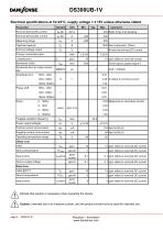
DS300UB-1V Electrical specifications at Ta=23°C, supply voltage = ± 15V unless otherwise stated Parameter Nominal primary AC current Nominal primary DC current Measuring range Overload capacity Nominal voltage output Primary / secondary ratio Response time to a step current IPN 1 At nominal primary DC current 3.3333 15 ppm refers to nominal current Small signal, graphs figure 3 1 Linearity error Amplitude error 0.25 % refers to nominal current 0.02 Measured on secondary current noise Fluxgate excitation frequency Power supply voltages Positive current consumption Negative current...
Open the catalog to page 2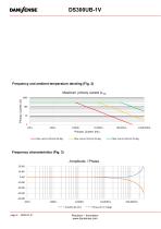
Frequency and ambient temperature derating (Fig. 2) Maximum primary current A rms Primary Current (A) Primary Current (Hz) Max current (Arms) 85 deg Precision – Innovation www.danisense.com
Open the catalog to page 3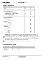
DS300UB-1V Isolation specifications Parameter Creepage distance Comparative tracking index (CTI) Rms voltage for AC isolation test, 50/60 Hz, 1 min - Between primary and (secondary and shield) - Between secondary and shield Impulse withstand voltage (1.2/50µs) Continous working voltage with Uninsulated wire • Non mains • CAT II (DC and rms) • CAT III (DC and rms) Insulated wire • Non mains • CAT II (DC and rms) • CAT III (DC and rms) Transient voltage with Uninsulated wire • Non mains • CAT II • CAT III Insulated wire • Non mains • CAT II • CAT III Caution: Do not connect the transducer to...
Open the catalog to page 4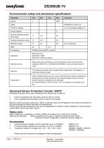
DS300UB-1V Environmental, safety and mechanical specifications Parameter Transient voltages Poution Degree Ambient operating temperature range Storage temperature range Relative humidity External devices External devices connected to current transducers must comply with the standards IEC61010-1, IEC60950 or IEC62368-1 and be energy-limited circuitry The transducer should only be cleaned with a damp cloth. No detergent or chemicals should be used. When multiple primary turns are used or high primary currents are applied the temperature around the transducer will increase, please monitor to...
Open the catalog to page 5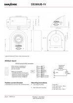
(general tolerance 0.3mm unless otherwise stat- DSUB pin layout DSUB-9 pinout & BNC connection When sensor is operating in normal condition the status pins are shorted. 9 8 7 6 Status pin properties. - Forward direction pin 8 to pin 3 - Maximum forward current 10mA - Maximum forward voltage 60V - Maximum reverse voltage 5V Positive current direction Mounting instructions Base plate mounting Is identified by an arrow on the transducer body Back side panel mounting Precision – Innovation www.danisense.com Impedance matching resistor 50Ω
Open the catalog to page 6
DS300UB-1V Intended use: The DS300UB-1V is designed to measure current up to 450A, and be powered by a DSSIU-4-1U or DSSIU-6-1U. Instruction for use: 1. Do not power up the device before all cables are connected. 2. Only use cables supplied by Danisense 3. Place the primary conductor through the apperture of the transducer 4. If the DSSIU-4(6)-1U is intended for desk use, mount the rubber feet which are part of the package. 5. If the DSSIU-4(6)-1U is intended for Rack mounting, use the screw kit for mounting and do not mount the rubber feet. 6. Connect a DSUB cable between DSSIU-4(6)-1U and...
Open the catalog to page 7All Danisense catalogs and technical brochures
-
DW500UB-2V
9 Pages
-
DN1000ID
8 Pages
-
DM1200ID-CD3000
6 Pages
-
DM1200ID
6 Pages
-
DS300UB-10V
7 Pages
-
DP50IP-B
4 Pages
-
DL2000UB-1V
6 Pages
-
DL2000UB-10V
6 Pages
-
VOM1333-10
1 Pages
-
DSSIU-6-1U
6 Pages
-
DSSIU-6-1U-V
7 Pages
-
DSSIU-4-1U
4 Pages
-
DS400UB-10V
6 Pages
-
DS200ID-CD1000
6 Pages
-
DS50ID
6 Pages
-
DC200IF
4 Pages


