- Company
- Products
- Catalogs
- News & Trends
- Exhibitions
DR5000UX-10V/7500A
1 /9Pages
DR5000UX-10V/7500A
1 /9Pages
Catalog excerpts
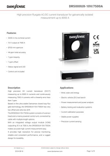
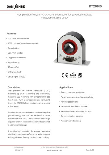
DR5000UX-10V/7500A High precision fluxgate AC/DC current transducer for galvanically isolated measurement up to 8000 A Features • 5000 A rms nominal current • Ø150 mm aperture • 44 ppm total accuracy • 7 ppm linearity • 7 ppm offset • Status signal and LED • Control unit included High precision DC current transducer (DCCT) measuring up to 8000 A currents and continuously measuring 7500 A currents with a linearity error less than 7 ppm. Based on the ultra stable Danisense closed loop flux gate technology, the DR5000UX-10V/7500A has very low offset and ultra low drift. The DR5000UX-10V/7500A system consists of a sensor head and a mains powered control unit, connected by • Wind, solar and energy • Electric vehicle (EV) test bench • Power measurement and power analysis • Battery testing and evaluation systems • Current calibration purposes • Stable power supplies cable with multiple length options. With an integrated voltage output module (VOM) • Precision current sensing outputting 10 V at 7500 A, the DR5000UX-10V/7500A makes accurate high current measurement easy. It provides high resolution for precise monitoring, reliable and consistent performance, and a rugged design for durability. All information subject to change without notice
Open the catalog to page 1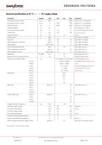
DR5000UX-10V/7500A Electrical specifications at 23 °C, Vs = ± 15 V supply voltage Parameter Nominal primary AC current Nominal primary DC current Overload capacity Nominal secondary voltage At nominal primary DC current Measuring range Transfer ratio Output resistance Linearity error Ratio temperature coefficient Ratio stability Offset (including earth field) Offset temperature coefficient Offset stability over time Response time to a step current IPN Total accuracy without offset Phase shift % of reading + % of full scale Full scale refers to IPN scale For other frequencies, see Linear interpolation...
Open the catalog to page 2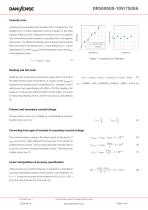
DR5000UX-10V/7500A Linearity error Linearity error is defined as the deviation from a straight line. The max current and another trendline is calculated from 0 to negative max current. The difference between each measured point and the squares method of the measurement points from 0 to positive Measurement Trendline linear trend line is the linearity error. The linearity error L can be expressed as (1), where Ireading is the measurement result Dato: 15. Novemberand 2012 Ifitted Linearity error straight line is a linear regression trend line based on the least Figure 1: Linearity error definition...
Open the catalog to page 3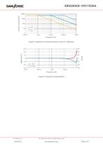
Primary current (Arms) Figure 2: Maximum continuous primary current vs. frequency Figure 3: Frequency characteristics All information subject to change without notice
Open the catalog to page 4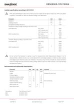
DR5000UX-10V/7500A Isolation specifications according to IEC 61010-1 When using REINFORCED insulated wire, all wiring must be insulated for the highest voltage used. When using BASIC insulated or uninsulated wire, follow the specified voltages in the table below: Parameter Creepage distance Comparative tracking index (CTI) Continuous working voltage according to IEC 61010-1 with: Uninsulated wire: CAT III (dc and rms) BASIC insulated wire: Transient voltage according to IEC 61010-1 with: Uninsulated wire: CAT III BASIC insulated wire: Do not connect the transducer to signals or use for measurements...
Open the catalog to page 5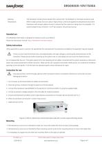
The transducer should only be cleaned with a damp cloth. No detergent or chemicals should be used. When multiple primary turns are used or high primary currents are applied the temperature around the transducer will increase, please monitor to ensure that the maximum ratings are not exceeded. It is recommended to have minimum 1 mm2 per ampere in the primary bus bar. The DR5000UX-10V/7500A is designed to measure current up to 8000 A. Please see the product manual: https://danisense.com/user-manual Safety instructions If the equipment is used in a manner not specified by the manufacturer, the protection...
Open the catalog to page 6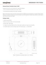
DR5000UX-10V/7500A Advanced Sensor Protection Circuits “ASPC” Developed to protect the current transducer from typical fault conditions: • Unit is un-powered and secondary circuit is open or closed • Unit is powered and secondary circuit is open or interrupted Both DC and AC primary current up to 100% of nominal value can be applied to the current transducers in the above situations without damage to the electronics. Please notice that the transducer core can be magnetized in all above cases, leading to a small change in Dato: 15. November 2012 output offset current (less than 10ppm) Package...
Open the catalog to page 7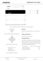
Voltage output Status Port Transducer Head Warning This apparatus must be earthed To prevent electric shock, disconnect AC line before removing cover Figure 6: Dimensions of electronics control box. 0.3 mm general tolerance Figure 7: XLR Mini voltage reading output pinout Positive current direction DRAWN Base plate mounting (Transducer head): 4 x 8 mm slotted holes, 6 Is identified by a label onCHECKED the housing. NNN APPR All measures in mm General tolerances: ± 0.1 LED SCALE When the sensor is operating in normal condition the status pins 1:4 Document number (Status+ and Status-) are shorted...
Open the catalog to page 8
Declaration of Conformity Danisense A/S Malervej 10 DK-2630 Taastrup Dato: 15. November 2012 Declares that under our sole responsibility that this product is in conformity with the provisions of the following EC Directives, including all amendments, and with national legislation implementing these directives: Directive 2014/30/EU Directive 2014/35/EU And that the following harmonized standards have been applied EEN 61010-1 (Third Edition):2010, EN 61010-1:2010/A1:2019 EN 61010-2-030:2021/A11:2021 EN 61326-1:2013 All DANISENSE products are manufactured in accordance with RoHS directive 2011/65/EU....
Open the catalog to page 9All Danisense catalogs and technical brochures
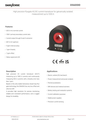 DS600ID
9 Pages
 DS400ID
9 Pages
 DS300ID
9 Pages
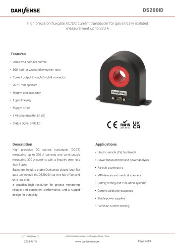 DS200ID
9 Pages
 DT200ID
8 Pages
 DT100ID
8 Pages
 DT50ID
8 Pages
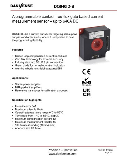 DQ640ID-B
7 Pages
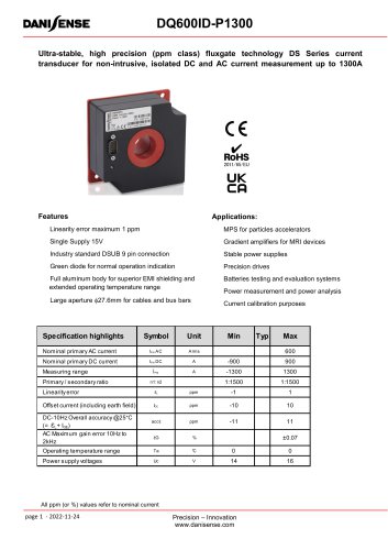 DQ600ID-P1300
7 Pages
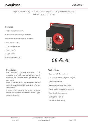 DQ600ID
9 Pages
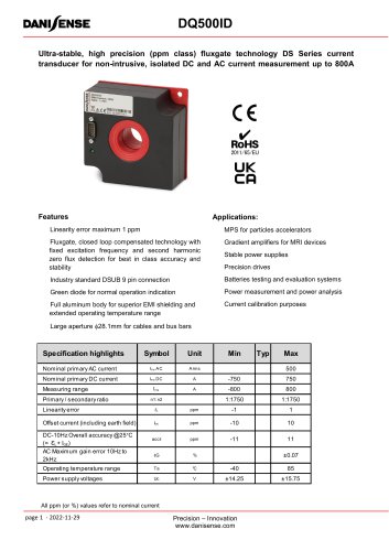 DQ500ID
7 Pages
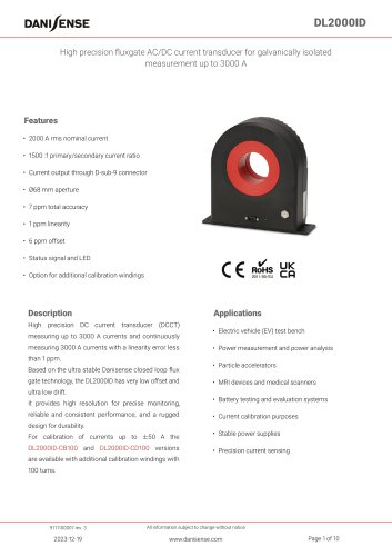 DL2000ID
10 Pages
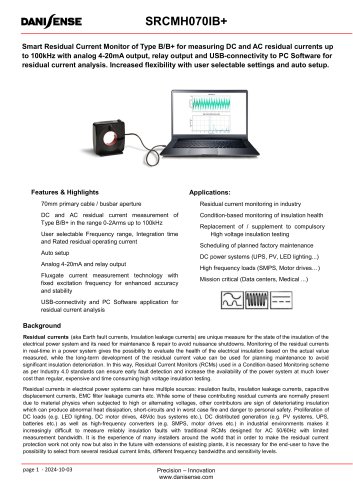 RCM Smart
10 Pages
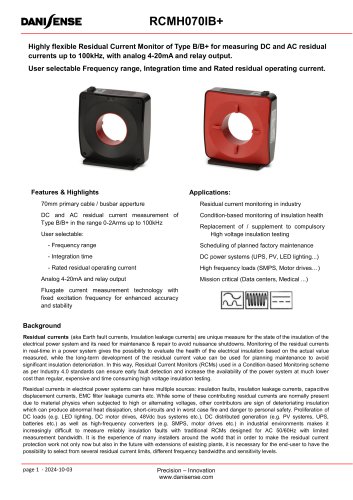 RCM Standard
9 Pages
 DSSIU-1
5 Pages
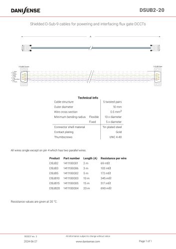 DSUB2-20
1 Page
 DSSIU-6-1U-V
8 Pages
 DSSIU-4-1U
6 Pages
 DS50ID
9 Pages
 DL2000UB-10V
9 Pages
 DL2000UB-1V
9 Pages
 DS300UB-1V
8 Pages
 DS300UB-10V
8 Pages
 DM1200ID-CD3000
7 Pages
 DN1000ID
9 Pages
 DW500UB-2V
9 Pages
 DM1200ID
8 Pages
 DSSIU-6-1U
7 Pages
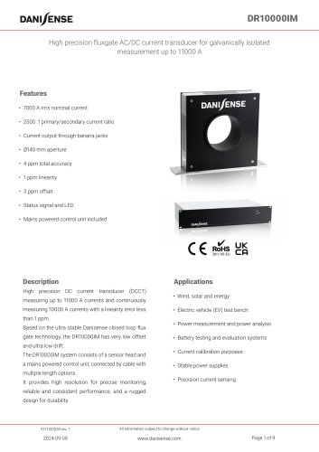 DR10000IM
9 Pages
 DR5000IM
9 Pages
 Product Selection Guide
24 Pages
 DP50IP-B
4 Pages
 VOM1333-10
1 Page
 DS400UB-10V
6 Pages
 DS200ID-CD1000
6 Pages
 DC200IF
4 Pages
- Optical cable
- Armored cable
- Twisted pair cable
- Interface module
- AC current transducer
- Precision current transducer
- Armored optical cable
- Fixed current transducer
- Monitoring current transducer
- Solid-core current transducer
- Through-hole current transducer
- High-accuracy current transducer
- Fluxgate current transducer
- Power optical cable
- Converter module
- Current output current transducer
- Voltage output current transducer
- Compact current transducer