- Catalogs
- Danfoss VLT Drives
- VLT® OneGearDrive
- Products
- Catalogs
- News & Trends
- Exhibitions
VLT® OneGearDrive
1 /40Pages

VLT® OneGearDrive
1 /40Pages
Catalog excerpts

ENGINEERING TOMORROW Operating Guide VLT® OneGearDrive
Open the catalog to page 1
4.4 Cage Clamp Connection Diagram 14 4.5 CleanConnect® Connection Diagram 15 5.1 Measures before Commissioning 16 MG75C702 Danfoss A/S © 12/2017 All rights reserved. 1
Open the catalog to page 3
5.1.3 Gear Unit Component 16 6 Maintenance, Diagnostics, and Troubleshooting 17 6.1.1 Replacing the Brake and Rotor 17 6.2 Inspection during Operation 18 8.2.1 Measures during Storage 22 8.2.2 Measures after Storage 22 8.3 Permanent Magnet 3-phase Synchronous Motor 22 8.5 General Specifications and Environmental Conditions 24 8.6.1 VLT® OneGearDrive Standard 25 8.6.2 VLT® OneGearDrive Standard with Torque Arm in Front Position (Optional) 26 8.6.3 VLT® OneGearDrive Hygienic 26 8.6.4 VLT® OneGearDrive Hygienic with Torque Arm in Front Position (Optional) 28 2 Danfoss A/S © 12/2017 All rights reserved....
Open the catalog to page 4
8.8.1 Accessories for VLT® OneGearDrive Standard 32 8.8.2 Accessories for VLT® OneGearDrive Hygienic 32 MG75C702 Danfoss A/S © 12/2017 All rights reserved. 3
Open the catalog to page 5
Table 1.1 Document Version 1.3 Disclaimer No liability is assumed for any damage or breakdown resulting from: • Failure to observe the information in the instruction manuals. • Unauthorized modifications to the VLT® OneGearDrive. • Operator error. • Improper work on or with the OneGearDrive. 1.1 Purpose of the Manual The purpose of this operating guide is to describe the VLT® OneGearDrive. The operating guide contains information about: • Safety. The VLT® OneGearDrive is available with 2 different motor types: • LA10 (type code L09), service period since August 2015. • V210 (type code L06), since...
Open the catalog to page 6
Operating Guide CAUTION Low-voltage machines are components for installation in machines in the sense of the machinery directive 2006/42/EC. Do not use the machine until conformity of the final product with this directive is established (refer to EN 60204-01). Any use not expressly approved by Danfoss constitutes misuse. This also applies to failure to comply with the specified operating conditions and applications. Danfoss assumes no liability of any sort for damage attributable to improper use. 1.6 Disposal Do not dispose of equipment containing electrical components together with domestic...
Open the catalog to page 7
2 Safety 2.1 Safety Symbols The following symbols are used in this guide: AWARNING Indicates a potentially hazardous situation that could result in death or serious injury. ACAUTION Indicates a potentially hazardous situation that could result in minor or moderate injury. It can also be used to alert against unsafe practices. Indicates important information, including situations that can result in damage to equipment or property. 2.2 Qualified Personnel All necessary work on electric drive units must only be performed by adequately qualified personnel (for example electrical engineers as specified...
Open the catalog to page 8
Mechanical Installation Operating Guide 3.1.1 Items Supplied The items supplied with the VLT® OneGearDrive are: • The OneGearDrive. • Plastic cap for eyebolt opening. • Hollow shaft cover with 3 washers and fixing screws. • Disc and retaining ring. 3.2.1 Inspection on Receipt After receiving the delivery, immediately check whether the item supplied matches the shipping documents. Danfoss does not honor claims for faults registered later. Register a complaint immediately: • With the carrier, if there is visible transport damage. • With the responsible Danfoss representative, if there are visible...
Open the catalog to page 9
The maximum force based on bearing life is detailed in 3.5.1 Mounting Procedure 1. Fasten the VLT® OneGearDrive by its flange using the torque arm (see chapter 8.7.1 Torque Arm Set). 2. Attach the OneGearDrive on to the driven shaft using the means provided. Illustration 3.1 Maximum Force 8 Danfoss A/S © 12/2017 All rights reserved. MG75C702
Open the catalog to page 10
Mechanical Installation Operating Guide Mechanical Installation Operating Guide Table 3.1 Dimensions of Assembly Kit Items 1) Key length required for bmin is shown in Table 3.2. Adapt the key length according to the shaft length used (b) in Table 3.2. The dimensions shown could differ from the customer conditions and must potentially be changed by the customer. MG75C702 Danfoss A/S © 12/2017 All rights reserved. 9
Open the catalog to page 11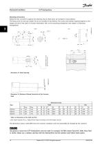
Mechanical Installation VLT® OneGearDrive Mounting instructions Rotate the disc (2) and fit it against the retaining ring (3). Both items are included in every delivery. The fixing screw (5) and lock washer (4) are not included in the delivery. The screws and washers required depend on the length and size of the shaft. For further information, refer to the mounting arrangement (see chapter 3.5 Mounting Arrangement). Mechanical Installation VLT® OneGearDrive Illustration 3.3 Axial Fastening Illustration 3.4 Maximum Allowed Eccentricity of the Conveyor Shaft Table 3.2 Dimensions of the Shaft and...
Open the catalog to page 12
Illustration 3.7 Assembly of the Mounting Arrangement and the Hollow Shaft Cover 3.7 Torque Restraint The VLT® OneGearDrive requires a suitable torque restraint to resist the reaction torque. The torque arm with mounting set is available as an option (see chapter 8.7.1 Torque Arm Set). Ensure that the torque arm does not create excessive constraining forces, for example due to the driven shaft running untrue. Excessive backlash can result in excessive shock torques in switching or reversing operations. 3.8 Final Assembly 1. Remove the red plastic screw if installed. 2. Remove the eyebolt (1)...
Open the catalog to page 13
4 Electrical Installation 4.1 EMC-compliant Installation To guarantee electromagnetic compatibility (EMC) as defined in EMC Directive 2014/30/EU, all signal lines must use shielded cables. The frequency converter operating guide indicates whether a shielded cable is necessary for the motor supply line. Adhere to the following instructions: • Ground the cable sheath at both ends. Ensure that hybrid cables are double-shielded. Always use shielded cables when laying signal cables and power cables parallel to each other. Ensure that the cable shields are connected to the terminal box. NOTICE It is...
Open the catalog to page 14All Danfoss VLT Drives catalogs and technical brochures
 Danfoss Drives VLT® Options
122 Pages
 VACON® 100
32 Pages
 VLT® Decentral Drive FCD 300
4 Pages
 VACON® NXP DCGuard™
90 Pages
 Danfoss Drives Options Portfolio
122 Pages
 VLT® 12-pulse drive
2 Pages
 DrivePro® Life Cycleservices
8 Pages
 TP5001 Range
92 Pages
 VLT® DriveMotor FCM 106
2 Pages
 VLT® DriveMotor FCM 300
2 Pages
 VLT® AutomationDrive
2 Pages
 VLT® AQUA Drive
2 Pages
 VLT® AQUA Drive
36 Pages
 VLT® drives up to 90 kW
2 Pages
 VLT® Panel Optimised Drives
2 Pages
 VLT® HVAC Drive
2 Pages
 VLT® HVAC Drive
40 Pages
 VLT® Drives FC Series
16 Pages
 Danfoss VLT Drives
8 Pages
 Danfoss Drives
12 Pages
 VLT®
VLT®20 Pages
 VLT 2800
34 Pages
 VLT® Product Catalogue
60 Pages
 VLT® Micro Drive
8 Pages
 VLT® HVAC Drive
40 Pages
 Harmonics mitigation
16 Pages
 VLT® Decentral Drive FCD 302
2 Pages
 Danfoss VLT® Softstarter
8 Pages
 VLT® OneGearDrive
2 Pages
 MCC 101 Sine wave filters
2 Pages
 VLT® Decentral FCD 300
8 Pages
 VLT® DriveMotor FCM 300
8 Pages
 VLT® 2800 Series
5 Pages
 VLT® AQUA Drive FC 200
16 Pages
 VLT® HVAC Drive FC 100
20 Pages


Archived catalogs

- Electromotor
- Compressor stage
- Air compressor
- Stationary compressor
- Alternating current motor
- Multipole motor
- Industrial compressor
- Asynchronous motor
- Reciprocating piston compressor
- Three-phase motor
- 4-pole motor
- 2-pole motor
- IP55 motor
- Protection relay
- Induction motor
- Electronic filter
- Gas compressor
- Passive electronic filter
- Frequency inverter