- Catalogs
- Danfoss VLT Drives
- TP5001 Range
- Products
- Catalogs
- News & Trends
- Exhibitions
TP5001 Range
1 /92Pages

TP5001 Range
1 /92Pages
Catalog excerpts

MAKING MODERN LIVING POSSIBLE TP5001 Range Electronic Programmable Room Thermostat Danfoss Heating Installation Guide
Open the catalog to page 1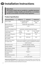
Installation Instructions Please Note: This product should only be installed by a qualified electrician or competent heating installer and should be in accordance with the current edition of the IEEE wiring regulations. Important note RFproducts: Ensure that there are no large metal objects, such as boiler cases or other large appliances, in line of sight between the transmitter and receiver as these will prevent communication between thermostat and receiver.
Open the catalog to page 2
First, remove the wallplate from the back of the unit. From the top left hand corner of the wallplate, there must be clearances of at least 15mm to the right, 15mm to the left, 30mm above and 100mm below in order to mount the plug-in module. Thermostat and Remote Room Sensor: Fix at a height of approximately 1.5m from the floor, away from draughts or heat sources such as radiators, open fires or direct sunlight. Installation Instructions Prior to mounting the unit the 2 DIL switches on the rear of the unit have to be moved to the required position. The factory presets are shown below. Sw. No. Keyboard...
Open the catalog to page 3
Cable Access Installation Instructions Wiring - TP5001 Output Connections, all hard wired models Battery Installation When installing the batteries in the TP5001 and TP5001 RF please ensure that the correct polarity is observed as per the markings on the inside of the battery compartment. Important: After installing the batteries press and release the RESET button to start the unit. The display may appear blank until this is done. Once the button is released the display will appear. All date, time, programming and override settings are maintained for the life of the product. I Some existing thermostats...
Open the catalog to page 4
Models with remote sensor inputs /D /E Terminal block for remote control/sensing is located on the circuit board above the battery compartment. Remote control connections 2) limit sensor, for example, floor temperature sensor (sold as accessory). 3) window contacts, card reader contacts or teleswitch contacts. See Installer Advanced Programming Options for set-up instructions. Window contact (NC) Window or teleswitch contact (NO or NC) Configured for window contact or other contact such as teleswitch Configured for remote room sensor or limit sensor Configured for window contact and other contact...
Open the catalog to page 5
Installation Instructions I M P O R TA N T To ensure that the factory programmes are set and the microcomputer is operating correctly it is essential that you press and hold the RESET button before you begin any commissioning or programming. Commissioning (RF models only) If the thermostat and the receiver have been supplied together in a combined pack, the units have been paired in the factory and no commissioning is required (RX1 only). To tune the RX receiver to the frequency of the thermostat signal, follow steps 1-5 below. Step 1 TP5001-RF Reset the unit by pressing the recessed reset button....
Open the catalog to page 6
TP5001 incorporates a number of advanced features which can be set by the user. These are accessed via a User Advanced Programming Mode, please refer to User Advanced Programming in the user instructions for details. Installer advanced programming options TP5001 incorporates an additional number of advanced features which can be set by the installer to improve the operating efficiency of the system and where required, to change the user functionality of the product. These are accessed via an Installer Advanced Programming Mode. These settings are optional and need only be made if there is a demand...
Open the catalog to page 7
Installation Instructions Option 30 - Set upper limit of temperature range Option 31 - Set lower limit of temperature range Option 32 - Enable Off at lower limit Option 33 - Enable On at upper limit
Open the catalog to page 8
Option 35 - Set integration time (Option 34 set to 3, 6, 9 or 12) (seek advice prior to adjusting) Installation Instructions Option 36 - Set temperature override rule
Open the catalog to page 9
Installation Instructions Option 37 - Set time duration of override rule (Option 36 set to 1 or 2) Option 38 - Relay state on low battery detect (battery products only) Option 40 - Number of Events per Day
Open the catalog to page 10
Option 70 - Keyboard disable rules Installation Instructions Option 71 - Random start rules (24V/230 Volt models only) Option 72 - Owner site reference number
Open the catalog to page 11
Installation Instructions Option 73 - Owner thermostat reference number Option 74 - Date format for calendar clock Option 81 - Thermstat calibration bias Option 90 - Define remote sensor type, "A" models only
Open the catalog to page 12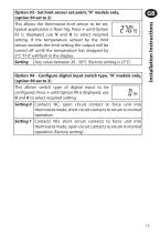
Option 94 - Configure digital input switch type, "A" models only, (option 90 set to 3)
Open the catalog to page 13
Installationsanleitung Bitte beachten Sie: Dieses Produkt darf nur von einem qualifizierten Elektriker oder Heizungsinstallateur gemaB der aktuellen Version der IEEE-Verkabelungsvorschriften installiert werden. Wichtiger Hinweis fur RF-Produkte: Achten Sie darauf, dass sich keine groBen metallischen Objekte wie Heizkesselgehause oder andere groBe Gerate in direkter Linie zwischen Sender und Empfanger befinden. Die Kommunikation zwischen Thermostat und Empfanger wird dadurch beeintrachtigt.
Open the catalog to page 14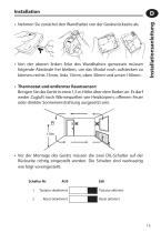
Installation • Nehmen Sie zunächst den Wandhalter von der Geräterückseite ab. • Von der oberen linken Ecke des Wandhalters gemessen müssen folgende Abstände frei bleiben, um das Modul noch aufstecken zu können: rechts 15mm, links 15mm, oben 30mm und unten 100mm. • Thermostat und entfernter Raumsensor: Bringen Sie das Gerät in etwa 1,5 m Höhe über dem Boden an. Es darf weder Zugluft noch Wärmequellen wie Heizkörpern, offenem Feuer oder direkter Sonneneinstrahlung ausgesetzt sein. • Vor der Montage des Geräts müssen die zwei DIL-Schalter auf der Rückseite richtig eingestellt werden. Die Schalter...
Open the catalog to page 15
Output Connections, all hard wired models NC Installation der Batterie Bitte beachten Sie, dass die Batterien korrekt in das Batteriefach des TP5001(A) bzw. TP5001 RF eingesetzt werden. Eine Darstellung dazu ist im Batteriefach vorhanden. Wichtig: Nachdem die Batterien eingesetzt wurden, drücken Sie bitte den RESET-Knopf, um den Thermostaten zu starten. Solange der RESETKnopf nicht gedrückt wurde, bleibt möglicherweise das Display leer. Nach Betätigen des RESET-Knopfes erscheint das Display. Alle Daten, die Uhrzeit, sämtliche Voreinstellungen und die vorgenommenen Einstellungen bleiben im Gerät...
Open the catalog to page 16All Danfoss VLT Drives catalogs and technical brochures
 Danfoss Drives VLT® Options
122 Pages
 VACON® 100
32 Pages
 VLT® Decentral Drive FCD 300
4 Pages
 VACON® NXP DCGuard™
90 Pages
 Danfoss Drives Options Portfolio
122 Pages
 VLT® OneGearDrive
40 Pages
 VLT® 12-pulse drive
2 Pages
 DrivePro® Life Cycleservices
8 Pages
 VLT® DriveMotor FCM 106
2 Pages
 VLT® DriveMotor FCM 300
2 Pages
 VLT® AutomationDrive
2 Pages
 VLT® AQUA Drive
2 Pages
 VLT® AQUA Drive
36 Pages
 VLT® drives up to 90 kW
2 Pages
 VLT® Panel Optimised Drives
2 Pages
 VLT® HVAC Drive
2 Pages
 VLT® HVAC Drive
40 Pages
 VLT® Drives FC Series
16 Pages
 Danfoss VLT Drives
8 Pages
 Danfoss Drives
12 Pages
 VLT®
VLT®20 Pages
 VLT 2800
34 Pages
 VLT® Product Catalogue
60 Pages
 VLT® Micro Drive
8 Pages
 VLT® HVAC Drive
40 Pages
 Harmonics mitigation
16 Pages
 VLT® Decentral Drive FCD 302
2 Pages
 Danfoss VLT® Softstarter
8 Pages
 VLT® OneGearDrive
2 Pages
 MCC 101 Sine wave filters
2 Pages
 VLT® Decentral FCD 300
8 Pages
 VLT® DriveMotor FCM 300
8 Pages
 VLT® 2800 Series
5 Pages
 VLT® AQUA Drive FC 200
16 Pages
 VLT® HVAC Drive FC 100
20 Pages


Archived catalogs

- Electromotor
- Compressor stage
- Air compressor
- Synchronous motor
- Stationary compressor
- Alternating current motor
- Multipole motor
- Industrial compressor
- Asynchronous motor
- Three-phase motor
- Reciprocating piston compressor
- 4-pole motor
- 2-pole motor
- IP55 motor
- Protection relay
- Induction motor
- Electronic filter
- Gas compressor
- Passive electronic filter
- Frequency inverter