
- Catalogs
- DANFOSS Refrigeration & Air Conditioning
- Level controls


Level controls

Level controls
The HFI high pressure float valve is designed for direct flange mounting on plate heat exchanger type condensers. It operates without requiring differential pressure and includes a purge valve for removing non-condensable gases. Suitable for R717 (ammonia), HCFC, and HFC refrigerants, it can withstand a maximum operating pressure of 25 bar g (363 psi g) and is constructed from special steel for low-temperature applications.
The valve is available with various connection types, including flange and butt-weld options, and is made from steel approved for low-temperature operation. It is suitable for a temperature range of –50/+80°C (–58/+176°F) and is CE marked under the Pressure Equipment Directive.
The HFI valve facilitates high pressure control by allowing refrigerant to expand from the condenser to the low-pressure side. It automatically equalizes pressure during off cycles, eliminating the need for a high-pressure receiver under normal conditions.
Capacity tables are provided for selecting the appropriate valve based on specific operating conditions. The valve's capacity must exceed the required capacity during nominal operation and plant start-up. For refrigerants other than ammonia, calculations must consider the refrigerant's density.
The valve's components are primarily made of steel, with specific grades listed for each part. The purge valve and gaskets are made from stainless steel and non-asbestos materials, respectively.
The document details the dimensions and specifications for inlet and outlet connections, including sizes in both metric and imperial units.
- Specifications: Lists various HFI models with dimensions and weights for both flanged and non-flanged versions, providing measurements in both metric and imperial units.
- Ordering Information: A comprehensive table outlines the code numbers for different valve configurations based on inlet connection size and nozzle size.
- Volumes: Internal and liquid volumes are specified for different operational levels.
- Technical Data: Used in refrigeration systems for ammonia or fluorinated refrigerants, CE marked and comply with the Pressure Equipment Directive.
- Design and Function: Describes the construction and operation of the SV regulators, including materials used and the function of each component.
- Capacity and Dimensioning: Detailed tables provide capacity values based on various conditions, including subcooling and pressure drop. Correction factors for different refrigerants are also included.
- Installation Guidelines: Recommendations for pipe dimensions and balance pipe connections are provided to ensure optimal performance and minimize pressure drops.
Discusses the design and function of modulating liquid level regulators, specifically types SV 1-3 and SV 4-6, used in refrigeration, freezing, and air conditioning systems. These regulators are designed for both high and low-pressure applications and can handle various refrigerants, including ammonia (R717).
The SV valves operate by modulating liquid levels in systems, ensuring stable regulation even during load changes. They can inject liquid into the float housing or directly into the evaporator.
Provides detailed technical specifications, including maximum working pressures, temperature ranges, and kv values for different SV types.
The SV valves are approved under the Pressure Equipment Directive (PED) and are CE marked. The materials used include low-temperature cast iron for valve housing and stainless steel for various components.
Includes capacity tables for different refrigerants and pressure drops, providing correction factors for subcooling.
A detailed breakdown of the valve construction is provided, listing materials and standards for each component.
Outlines application scenarios, such as using the valves in flooded evaporators and large systems with long pipelines.
Information on ordering spare parts and accessories is provided, including special orifice sizes for different capacities.
Provides technical specifications for modulating liquid level regulators, specifically the PMFL, PMFH, and SV types. These regulators are applicable to HCFC, HFC, and R717 (Ammonia) refrigerants.
The PMFL and PMFH systems are designed for modulating liquid level control in refrigeration, freezing, and air conditioning plants.
Provides examples for sizing PMFL and PMFH valves, using R717 (Ammonia) as the refrigerant.
The valve housing is made of low-temperature cast iron (spherical) - EN GJS 400-18-LT.
The PMFL and PMFH valves are CE marked in accordance with the Pressure Equipment Directive - 97/23/EC.
Dimensions and weights for the valves are likely included, although specific details are not provided in the excerpt.
- Design and Function: An electro-mechanical device for monitoring liquid levels in vessels and accumulators, capable of acting as a low/high-level alarm.
- Features: Includes DIN, ANSI, and FPT/NPT flanges, adjustable liquid level differential switch point, and an electric magnetic microswitch.
- Specifications: Suitable for HCFC, non-flammable HFC, and R717 (Ammonia) refrigerants.
- Materials: Constructed with cast iron, stainless steel, and polycarbonate components.
- Applications: Used in liquid over-feed accumulators, flooded surge drums, and high/low-pressure receivers.
- Technology: Utilizes Time Domain Reflectometry (TDR) or Guided Microwave technology to measure liquid levels.
- Versions: Available in cable and coaxial versions, suitable for various refrigerants including HCFC, non-flammable HFC, R717, and R744 (CO2).
- Features: Provides a 4-20 mA output signal proportional to the liquid level.
- Installation: The cable version requires installation in a standpipe, while the coaxial version can be installed directly in a vessel.
- Performance: Unaffected by dust, foam, vapour, or changes in liquid density.
- Detailed ordering codes and spare parts lists are provided for both AKS 38 and AKS 4100/4100U.
Discusses the installation and use of liquid level glasses, specifically for environments below -10°C (+14°F). It recommends using a sight adapter for insulation and an oil column in R717 plants to prevent bubble formation and ice build-up.
For R717 systems, outlines the oil charging process using synthetic oil type SHC 226.
Lists materials used in the construction of liquid level glasses, including steel for frames and flanges, glass for sight glasses, and non-asbestos gaskets and coatings.
Dimensions and weights for various types of liquid level glasses (LLG 185 - 1550) are provided.
Provides a detailed guide on ordering liquid level glasses, including type codes and configurations for different safety systems and accessories.
Catalog excerpts

High pressure float valve, HFI Contents Page Features . . . . . . . . . . . . . . . . . . . . . . . . . . . . . . . . . . . . . . . . . . . . . . . . . . . . . . . . . . . . . . . . . . . . . . . . . . . . . . . . . . . . . . . . . 345 Design . . . . . . . . . . . . . . . . . . . . . . . . . . . . . . . . . . . . . . . . . . . . . . . . . . . . . . . . . . . . . . . . . . . . . . . . . . . . . . . . . . . . . . . . . . . 346 Technical data . . . . . . . . . . . . . . . . . . . . . . . . . . . . . . . . . . . . . . . . . . . . . . . . . . . . . . . . . . . . . . . . . . . . . . . . . . . . . . . . . . . 346 The principle of high pressure control . . . . . . . . . . . . . . . . . . . . . . . . . . . . . . . . . . . . . . . . . . . . . . . . . . . . . . . . . . . . . 346 Insert for the high pressure float valve . . . . . . . . . . . . . . . . . . . . . . . . . . . . . . . . . . . . . . . . . . . . . . . . . . . . . . . . . . . . 347 Computation and selection . . . . . . . . . . . . . . . . . . . . . . . . . . . . . . . . . . . . . . . . . . . . . . . . . . . . . . . . . . . . . . . . . . . . . . . 347 High pressure control in refrigeration system with condenser/evaporator . . . . . . . . . . . . . . . . . . . . . . . . . 350 Material specification . . . . . . . . . . . . . . . . . . . . . . . . . . . . . . . . . . . . . . . . . . . . . . . . . . . . . . . . . . . . . . . . . . . . . . . . . . . . 351 Connections . . . . . . . . . . . . . . . . . . . . . . . . . . . . . . . . . . . . . . . . . . . . . . . . . . . . . . . . . . . . . . . . . . . . . . . . . . . . . . . . . . . . . 352 Dimensions and weights . . . . . . . . . . . . . . . . . . . . . . . . . . . . . . . . . . . . . . . . . . . . . . . . . . . . . . . . . . . . . . . . . . . . . . . . . 353 Volumes . . . . . . . . . . . . . . . . . . . . . . . . . . . . . . . . . . . . . . . . . . . . . . . . . . . . . . . . . . . . . . . . . . . . . . . . . . . . . . . . . . . . . . . . . 355 Ordering . . . . . . . . . . . . . . . . . . . . . . . . . . . . . . . . . . . . . . . . . . . . . . . . . . . . . . . . . . . . . . . . . . . . . . . . . . . . . . . . . . . . . . . . . 355 HFI with 2 external connections . . . . . . . . . . . . . . . . . . . . . . . . . . . . . . . . . . . . . . . . . . . . . . . . . . . . . . . . . . . . . . . . . . 355
Open the catalog to page 1
MAKING MODERN LIVING POSSIBLE High pressure float valve HFI HFI is a high pressure float valve with internal liquid measuring device. The float valve is designed for direct flange mounting or welding on to plate heat exchanger type condensers, as illustrated in fig 1. HFI is direct acting, therefore no differential pressure is required to activate the valve. HFI is sturdy and reliable owing to its simple design. The float valve is equipped with a purge valve for purging non condensable gases e.g. air from the top of the valve housing. This facility is also useful if the valve has to be serviced....
Open the catalog to page 3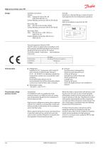
High pressure float valve, HFI Design Available connections Flange: Inlet: Flange DN 100 or DN 150 (DIN-2635/DIN 2512-F) Outlet: Welding connection DN 50 (EN 10220) Housing Housing i.e. shell and flange is made of special steel approved for low temperature operation. Butt-weld, DIN: Inlet: DN 100 or DN 150 (EN 10220) Outlet: Welding connection DN 50 (EN 10220) Installation Refer to installation instruction for HFI. Butt-weld, ANSI: Inlet: DN 100 (4 in.) or DN 150 (6 in.) (ANSI B 36.10) Outlet: Welding connection DN 50 (2 in.) (ANSI 36.10) Pressure Equipment Directive (PED) The HFI-valves are...
Open the catalog to page 4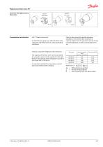
High pressure float valve, HFI Insert for the high pressure float valve Detail B Fully open Detail A Fully closed In R 717 plants (ammonia) On the following pages you will find tables with capacities of the float valve at various operating conditions. In plants using other refrigerants than ammonia The capacity of the float valve can be calculated by using the values and the equation to the right. However, the density of the refrigerant must be in the range: 500 to 700 kg/m3. For densities outside this range please contact your local Danfoss Sales Company. Select a valve using the specific operating...
Open the catalog to page 5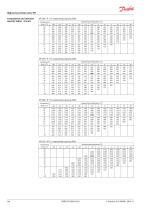
High pressure float valve, HFI Computation and selection capacity tables - SI units HFI 040 - R 717, evaporating capacity [kW] Evaporating temperature (°C) HFI 050 - R 717, evaporating capacity [kW] Evaporating temperature (°C) HFI 060 - R 717, evaporating capacity [kW] Evaporating temperature (°C) HFI 070 - R717, evaporating capacity [kW] Condensing temp. (°C)
Open the catalog to page 6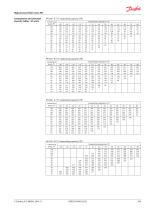
High pressure float valve, HFI Computation and selection capacity tables - US units HFI 040 - R 717, evaporating capacity [TR] Evaporating temperature (°F) HFI 050 - R 717, evaporating capacity [TR] Evaporating temperature (°F) HFI 060 - R 717, evaporating capacity [TR] Evaporating temperature (°F) HFI 070 - R717, evaporating capacity [TR] Condensing temp. (°F)
Open the catalog to page 7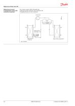
High pressure float valve, HFI High pressure control in refrigeration system with condenser/evaporator Fig. 5 shows a water chiller with plate heat exchanger as both condenser and evaporator. HFI is flanged directly on to the condenser. Compressor Vapor Liquid High pressure Float Valve - HFI High pressure condenser Water chiller (evaporator)
Open the catalog to page 8
High pressure float valve, HFI Material specification Part Material Housing: a. Shell Steel b. Flange (shell) Steel c. Flange (inlet) Steel d. Branch (discharge) Steel e. External connection Steel f. Flange (shell) Steel g. Connecting tube Steel 3 End cover with cylinder Steel 4 Set screw Stainless steel 5 Tube Steel 6 Gasket Aluminium 7 Purge valve, SNV-ST 1) 8 Gasket Non asbestos 9 Float Ball Steel 1 ) for further information please see the technical brochure for SNV-ST valves.
Open the catalog to page 9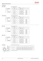
High pressure float valve, HFI Connections DIN - Outlet Butt welding EN10220 Size mm For use with valve type ANSI - Outlet Butt welding ANSI B 36.10 Size mm For use with valve type Butt welding EN 10220 Size mm ANSI - Inlet For use with valve type Butt welding ANSI B 36.10 Size mm Inlet flange Inlet For use with valve type *Inlet flange and DIN outlet
Open the catalog to page 10All DANFOSS Refrigeration & Air Conditioning catalogs and technical brochures
 ICLX
ICLX25 Pages
 Shut-off ball valve Type GBC
15 Pages


Archived catalogs
 Danfoss Industrial Refrigeration
32 Pages
 VSH088-G
28 Pages
 Danfoss scroll VZH serie
6 Pages
 Danfoss scroll VSH serie -
56 Pages
 VZH028-VZH044
4 Pages
 CXH140
6 Pages
 Counterfeit
3 Pages
 ADAP-KOOL ® Catalogue
222 Pages
 Electromechanical controls
58 Pages
 compressors MT - MTZ - NTZ
8 Pages
 Quick Selection Catalogue
359 Pages
 MCX General Catalogue
48 Pages
 EVR
EVR2 Pages
 R32 brochure
5 Pages
 Apexx™ SLV series
8 Pages
 SGN+ and SGI+ sales brochure
2 Pages


- Manual valve
- Control valve
- Ball valve
- Temperature probe
- Electrically operated valve
- Regulating valve
- Flange valve
- Liquid filter
- On/off valve
- Flap valve
- Check valve
- Resistance temperature sensor
- Lever valve
- Electric valve
- Pressure transmitter
- Gas solenoid valve
- 2-way solenoid valve
- NC solenoid valve
- Level limit switch